4 grouting – Flowserve HED Worthington User Manual
Page 17
HED/HED-DS USER INSTRUCTIONS ENGLISH 85392695 – 06/14
Page 17 of 64
pads. Levelling is best achieved by adjusting the
shim pack thickness under each holding bolt.
Carefully raise the baseplate by using either the
baseplate jacking screws provided or by levering
with a suitable pinch bar or by installing a low
level hydraulic jack.
b) Adjust the shim pack thickness and lower the
baseplate.
c) Repeat this procedure in a logical manner at
each bolt position until the baseplate is both
straight and levelled. A degree of 0.25 mm per
metre (0.0035 inch per foot) length is achievable
on most units with a maximum of 0.40 mm per
meter length (0.005 inch per foot).
d) In case of installation on steel structures (like
platforms) proceed with these extra steps:
Using a calibrated pin with a cone point mark
the centre of baseplate support pads
mounting holes on the soleplate.
Lift and move away the pump skid.
Drill and tap the soleplate fixing holes.
Replace the pump skid so that the soleplate
fixing holes align with the baseplate support
pads mounting holes.
Level the unit like done previously (see points
a, b, c).
e) When the baseplate is level, pull down the
foundation bolts so they are snug or tighten the
fixing bolts in case of installation on steel
structure. This may have disturbed the baseplate,
so re-check the levels.
Ensure that shaft alignment per Section 4.5 can be
achieved prior to grouting the baseplate.
4.4 Grouting
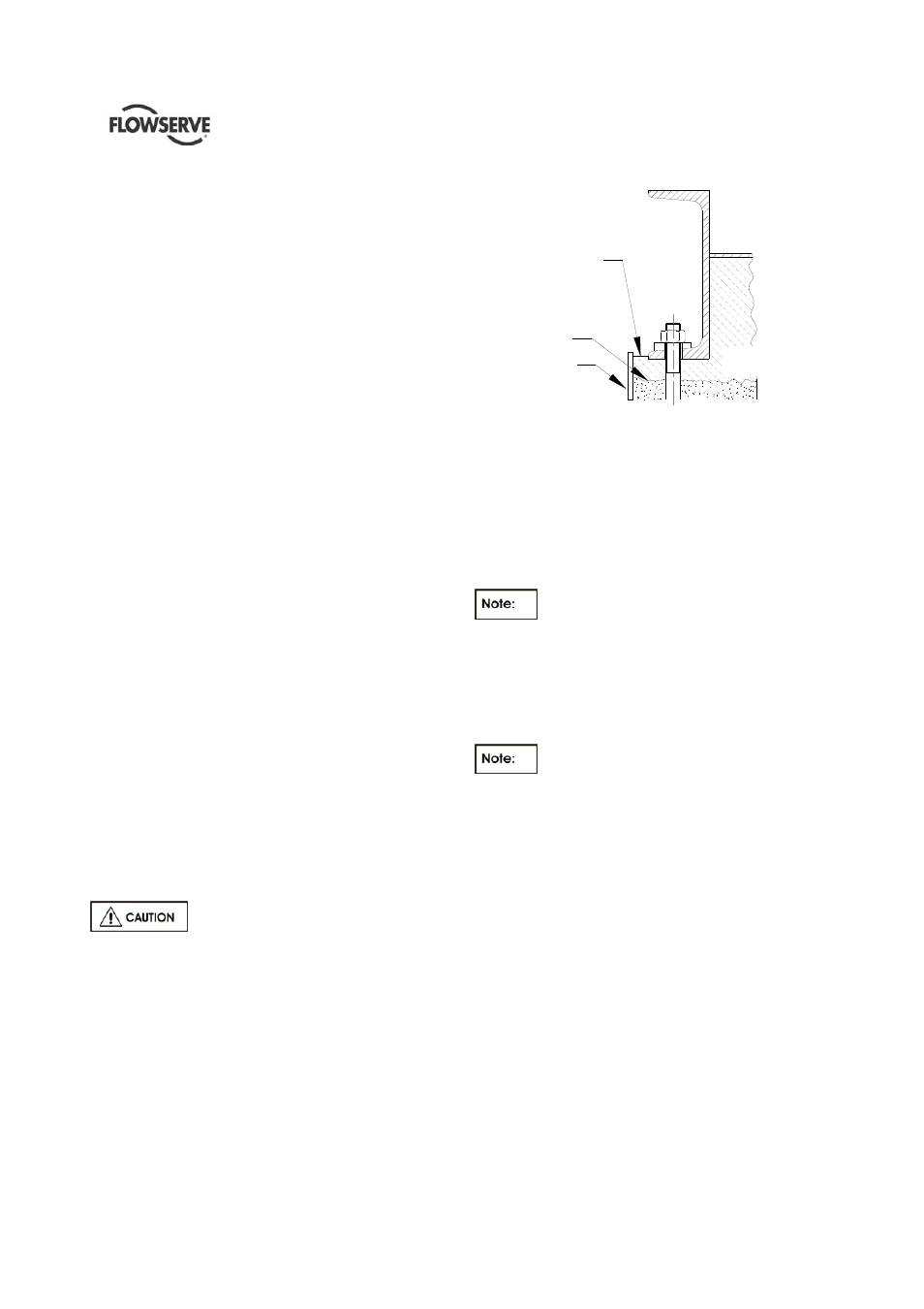
Build a dam around the foundation as shown in
Figure 4.4 after levelling the baseplate. It is a matter
of personal preference whether the levelling wedges
under the baseplate should be removed after
grouting. If you do not want to remove the wedges,
carefully mark their locations before pouring grout.
Before grouting, level machined
pads of baseplate in both directions and perform
a rough shaft/coupling alignment. Alignment after
grout has set will not be possible if above is not
satisfactorily completed.
4.4.1 Fully Grouted Baseplates
DAM
CONCRETE
LEAVE TOP OF
FOUNDATION ROUGH
DO NOT FINISH
WITH TROWEL
FINISHED GROUT
GROUTING 1 TO 2
INCHES DEEP
Figure 4.4
Use a good, high strength, non shrink grout mix and
install as per manufacturer's instructions.
Holes are provided in the baseplate to permit pouring
the grout and stirring while acting as air vents. Fill
under the baseplate completely, stirring to assure
correct distribution of the grout. Check to see that the
grout flows under the edges of the baseplate evenly.
Do not vibrate baseplate when grouting,
making sure baseplate is vented correctly and all
areas are thoroughly puddle to prevent any resonant
problems.
When the grout is thoroughly hardened, remove the
dam and wedges, if desired, filling in the holes they
leave with grout.
Pour grout until level reaches top of dam.
Allow to dry sufficiently to prevent grout from
overflowing while completing the remaining grouting.
4.4.2 Baseplate not Intended for Grouting but
Installed on Concrete Foundations
According to the figure 4.3.1 and 4.4.1 the baseplate
will not be grouted but only a sealing shall be
provided. During the preparation, as indicated on the
General Arrangement drawing a certain number of
openings into the sealing must be guaranteed. After
the sealing the blocks used to realise the openings
must be removed. Blocks have to be wider than the
baseplate longitudinal beam in order to guarantee the
opening for the drainage.