9 assembly – Flowserve HED Worthington User Manual
Page 42
HED/HED-DS USER INSTRUCTIONS ENGLISH 85392695 – 06/14
Page 42 of 64
c) Labyrinth seals and bearing isolators should be
inspected for damage but are normally non-
wearing parts and can be re-used.
d) Bearing seals are not totally leak free devices.
Oil from these may cause staining adjacent to the
bearings.
6.9 Assembly
To assemble the pump consult the sectional
drawings, see section 8, Parts list and drawings.
Ensure threads, gasket and O-ring mating faces are
clean.
6.9.1 Wear rings
The impeller is fitted with both front and rear wear
rings.
The impeller rings are renewable and should be
replaced when badly grooved, and/or when pump
performance does not meet the system requirements.
Whenever it becomes necessary to replace either
wear ring, both rings involved (impeller and casing
cover) must be ordered and replaced as a set as they
are furnished standard size only.
Spare impeller wear rings are supplied with a material
stock over outside diameter which has to be
machined off after rings fitting on impeller.
If an impeller with its wear rings is ordered as spare,
it will be supplied fully machined, including wear rings
outside diameter, to original dimensions. Casing
Cover wear rings are always supplied fully machined.
Be sure to re-establish the original running clearance
between the two wear rings involved by machining
the fitted impeller rings.
6.9.1.1 Impeller wear rings
a) To remove impeller wear rings, mutually remove
wear ring set screws or ground off tack weld.
Rings can be machined off or grind two slots
diametrically opposite across the width of the ring
so it can be split apart. Use caution if ring is
removed by grinding so as not to damage
impeller hubs.
IMPELLER
HAND
GRINDER
IMPELLER
RING
Figure 6.3
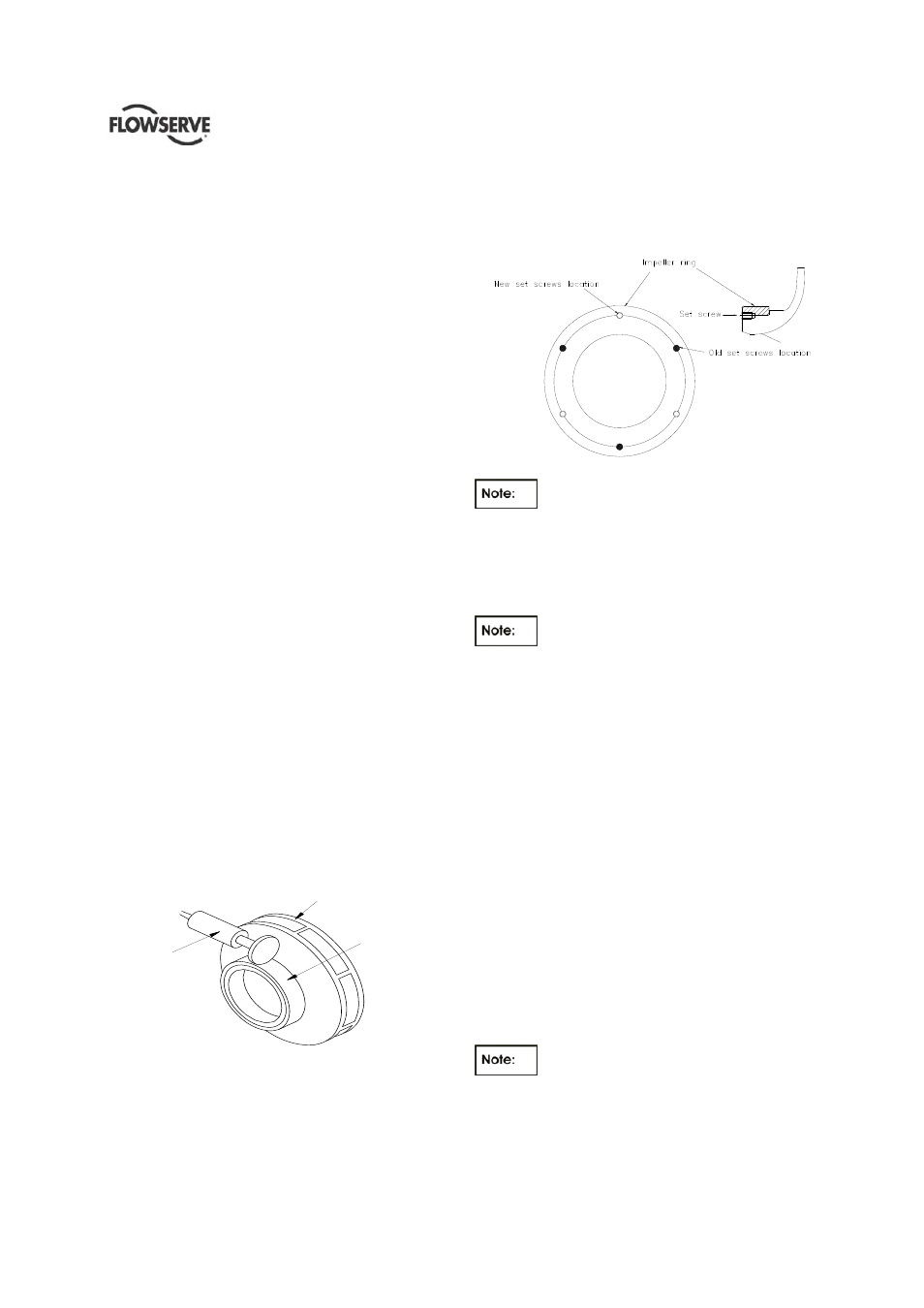
b) Make sure ring fits on impeller are free of nicks or
burrs. Heat new ring to 107 °C (225 °F) and
install on impeller. Drill and tap new holes in
impeller spaced half the circular distance from the
previously used holes in the impeller. See sketch
below.
Figure 6.4
Impeller wear rings when installed must
be machined to establish original diameter and
running clearance. Whenever an impeller has new
wear rings fitted it must be dynamically balanced
before being reassembled. Refer to the Cross
Sectional drawing for the requested running
clearance.
The impeller wear ring bore is relieved at
one edge. Ensure that the ring is installed on the
impeller so that the chamfered edge is sitting
against the impeller.
6.9.1.2 Casing cover wear rings
Each wear ring is locked against rotation with a
cylindrical pin.
a) To remove the wear ring, press it out. If this
method does not easily effect removal of the ring,
it can be split apart. First, however, drill one or
more holes in the face of the worn ring.
New rings to be installed must be shrunk by freezing -
20°C (-4°F) when installing in casing cover. Fit and
secure with a locking pin. Replacement wear rings
are furnished standard size in the bore. Check the
running clearance between impeller and casing ring
against the appropriate value.
6.9.2 Rotor Assembly
a) Install central shaft sleeve onto the shaft.
b) Place 1st and 2nd stage impeller key in relevant
shaft key-way.
Take care to mount the impeller so that
the vane tips point away from the apparent flow
direction (See below fig).