Flowserve HED Worthington User Manual
Page 21
HED/HED-DS USER INSTRUCTIONS ENGLISH 85392695 – 06/14
Page 21 of 64
Maximum forces and moments allowed on the pump
flanges vary with the pump size and type. To
minimize these forces and moments that may, if
excessive, cause misalignment, hot bearings, worn
couplings, vibration and the possible failure of the
pump casing, the following points should be strictly
followed:
Prevent excessive external pipe load.
Never draw piping into place by applying force to
pump flange connections.
Do not mount expansion joints so that their force,
due to internal pressure, acts on the pump flange.
Ensure piping and fittings are flushed
before use.
Ensure piping for hazardous liquids is arranged
to allow pump flushing before removal of the pump.
4.6.2 Suction Piping
a) The inlet pipe should be one or two sizes larger
than the pump inlet bore and pipe bends should
be as large radius as possible.
b) Keep the suction pipe free of all air pockets.
(Vent is required).
c) Pipework reducers should have a maximum total
angle of divergence of 15 degrees.
d) Use only eccentric reducers with the straight side
on the top.
e) Flow should enter the pump suction with uniform
flow, to minimize noise and wear.
f) A gate valve is recommended in the suction line.
g) Except if considerable foreign matter is expected
strainers are not recommended in inlet piping.
Inlet strainers, when used, should have a net
“free area” (see section 4.6.2.1)
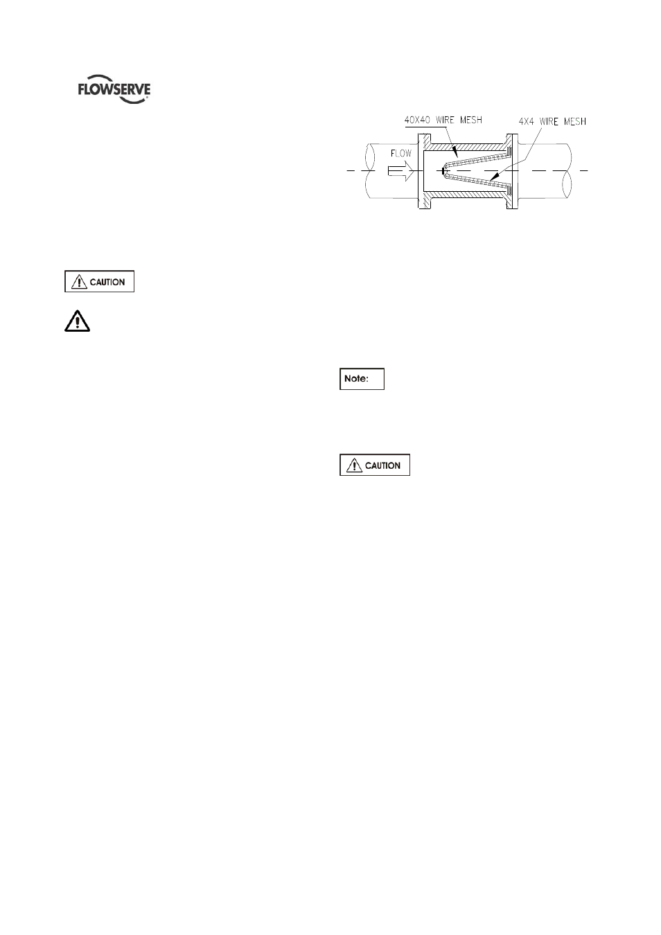
4.6.2.1 Suction Strainer
It is recommended that a temporary strainer be
placed in the suction pipe to prevent lodging of
foreign material in the impeller. A pipe spool of
sufficient size should be provided with gauge taps to
accommodate the suction strainer.
The strainer should be installed as close to the pump
as possible. The open area of the strainer should
have a minimum of a 3 to 1 ratio to the area of the
pump inlet.
Pressure gauges should be installed on both sides of
the strainer, so the pressure drop across the strainer
can be measured when the unit is operated.
Typical temporary suction strainer
Pressure gauges should be installed on both sides of
the screen so that the pressure drop across the
screen can be measured.
When the unit is being started, the gauges on each
side of the screen should be carefully watched. An
increase in the differential pressure between the two
gauges indicates that the screen is becoming clogged
with dirt and scale. At this point, the pump should be
shut down, and the screen cleaned and/or replaced.
A spool piece should be installed in
suction line so that the suction strainer may be
installed and removed with a pressure gauge
between the strainer and pump.
4.6.2.2 Bypass Line
Operation at low flows results in
pump horsepower heating the liquid. A bypass
may be required to prevent vaporization and
subsequent pump damage. Refer to local
FLOWSERVE branch to determine if a bypass is
required. Mechanical damage may result from
continuous operation at flows less than specified.
4.6.3 Discharge piping
a) Install a check valve and a gate valve in the
discharge pipe of the pump. When the pump is
stopped, the check valve will protect the pump
against excessive pressure and will prevent the
pump from running backward. The check valve
should be installed between the gate valve and
the pump nozzle in order to permit its inspection.
Never throttle pump on suction side and never
place a valve directly on the pump inlet nozzle.
b) Pipework reducers should have a maximum total
angle of divergence of 15 degrees.
4.6.4 Drains and Vents
Pipe pump casing drains and vent to a convenient
disposal point.
Jacket piping
The stuffing boxes are jacketed for water cooling and
also the bearing brackets can be jacketed. They