Flowserve HED Worthington User Manual
Page 20
HED/HED-DS USER INSTRUCTIONS ENGLISH 85392695 – 06/14
Page 20 of 64
If the motor does not run in its
magnetic centre the resultant additional axial force
may overload the pump thrust bearing.
Complete piping as below and see sections 4.7,
“Final shaft alignment check” up to and including
section 5, “Commissioning, start-up, operation and
shutdown” before connecting driver and checking
actual rotation.
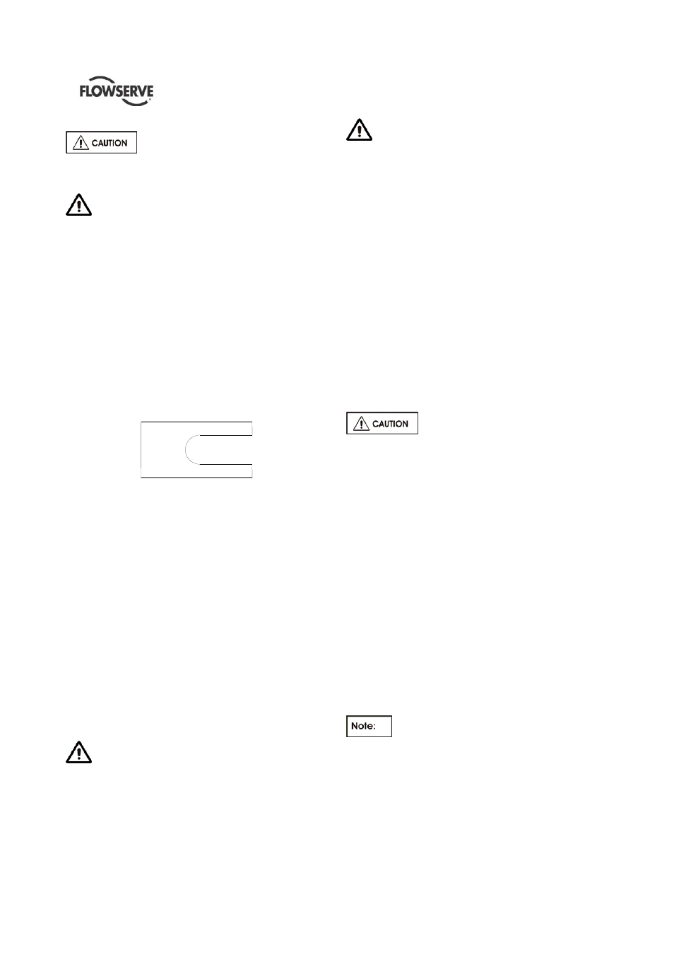
4.5.3 Shims
The shims between the equipment feet and mounting
surface should be clean and dry. This is especially
critical for pumps in service for sometime and need to
be realigned. Water, dirt and rust may change the
height of the shim pack over a period of time. Shims
should be made large enough to support the weight
of the equipment on its mounting foot. Do not use
many thin shims as this may result in a spongy
mounting.
Figure 4.12
Recommended shim design
Move the equipment vertically by adding or removing
the calculated thickness of shims. Torque holding
down bolts to required values.
4.5.4 Hot alignment – Pump and driver dowels
Pump hold down bolts are to be torqued down and
dowel pins are to be located in pump feet. (This is
only applicable if Hot Alignment is required).
Refer to driver outline drawing and/or driver
instructions for driver doweling information.
A hot check can only be made after the unit has been
in operation a sufficient length of time to assume its
NORMAL operating temperature and conditions. If
the unit has been correctly cold set, the offset
misalignment will be within
within the limits stated on
par 4.5.2.2
when in operation.
If not make adjustments.
Do not attempt any maintenance,
inspection, repair or cleaning in the vicinity of
rotating equipment. Such action could result in
injury to operating personnel.
Before attempting any inspection or repair
on the pump the driver controls must be in the
"off" position, locked and tagged to prevent
restarting equipment and injury to personnel
performing service on the pump.
4.5.5 Assemble coupling
a) Assemble coupling as per the manufacturer's
instructions included in Appendix of this manual.
b) Install
coupling
guard
4.5.6 Installation check list
a) Level
Baseplate?
b) Grout Baseplate - Check Foundation Bolts?
c) Alignment
Shaft/Coupling?
d) Piping Installed - Correct Vent, Gauge, Valve,
Suction Strainer Locations?
e) All Flange Bolting Correctly Torqued with
appropriate gaskets in place?
f) Check
Shaft/Coupling
Alignment
again.
g) Coupling guard correctly installed ?
4.6
Piping
Never use the pump as a support for
piping.
4.6.1 General
These units are furnished for a particular service
condition. Changes in the hydraulic system may
affect performance adversely. This is especially true if
the changes reduce the pressure at the suction or if
the liquid temperature is increased. In case of doubt
contact FLOWSERVE.
Suction and discharge piping should be of ample
size, be installed in direct runs, and have a minimum
of bends. Double bends must be avoided in suction
line and a straight run of pipe, equal 7 to 10 times the
pipe diameter is desired directly upstream of the
suction nozzle.
In order to minimize friction losses and hydraulic
noise in the pipework it is good practice to choose
pipework that is one or two sizes larger than the
pump suction and discharge. Typically main pipework
velocities should not exceed 2 m/s (6 ft/sec) suction
and 3 m/s (9 ft/sec) on the discharge.
Provision must be made to support piping
external to the pump to prevent excessive nozzle
loads, maintain pump/driver alignment and avoid pipe
induced vibrations.
Take into account the available NPSH which must be
higher than the required NPSH of the pump.