Flowserve ESP3 User Manual
Page 20
ESP3 USER INSTRUCTIONS ENGLISH 26999943 08-11
Page 20 of 64
4.7.3 Discharge piping
Install a valve in the discharge line. This valve is
required for regulating flow and/or to isolate the
pump for inspection and maintenance.
When fluid velocity in the pipe is
high, for example, 3 m/s (10 ft/sec) or higher, a
rapidly closing discharge valve can cause a
damaging pressure surge. A dampening
arrangement should be provided in the piping.
All piping must be independently supported,
accurately aligned and preferably connected to the
pump by a short length of flexible piping. The pump
should not have to support the weight of the pipe. It
should be possible to install discharge bolts through
mating flanges without pulling or prying either of the
flanges. All piping must be tight.
a)
Use discharge piping one size larger than the
pump discharge.
b)
Discharge piping should be well supported
and connected to the pump such that no strain
or weight of the piping is carried by the pump.
c)
Check pump shaft for freedom of rotation by
hand to make sure any discharge piping strain
is not causing binding.
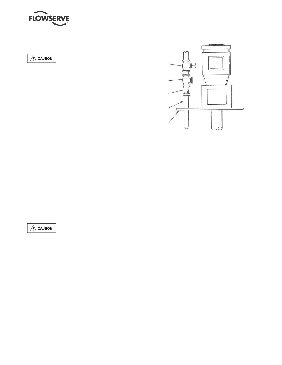
d)
After the pump discharge, the increaser
should be the first item in the discharge line,
followed by the check valve and gate valve,
respectively. See Figure 4-1.
e)
It is recommended that pressure indicating
devices be installed before and after the
valves in the discharge line to verify the pump
is not being run dry and that the discharge
valves are not closed.
The check valve is required to
prevent back-flow through the pump on shut-down.
This flow can reverse rotation of the pump,
potentially damaging the pump, motor and
associated equipment.
Figure 4-1
GATE
VALVE
CHECK
VALVE
CONCENTRIC
INCREASER
PUMP.
DISCHARGE
MOUNTING,
PLATE