Flowserve ESP3 User Manual
Page 48
ESP3 USER INSTRUCTIONS ENGLISH 26999943 08-11
Page 48 of 64
the packaging they should only come in contact with
clean hands, fixtures, tools and work surfaces.
Pump Group
Size
GP1 – 1E
GP2 – 2E
GP3 – 3E
Ball Bearing
Size
7308
7310
7313
Bearings have a slight interference fit
which requires that they be pressed on the adjuster with
an arbor or hydraulic press. Even force should be
applied to only the inner race. Never press on the outer
race, as the force will damage the balls and races.
An alternate method of installing bearings is to heat
the bearings to 93 °C (200 °F) by means of an oven
or induction heater. With this approach the bearing
must be quickly positioned on the adjuster.
Never heat the bearings above 110 °C (230 °F). To
do so will likely cause the bearing fits to permanently
change, leading to early failure.
Duplex angular contact bearings must be mounted
face-to-face with the wider thrust sides of the outer
races away from each other as shown in figure 6-10.
Only bearings designed for universal mounting
should be used. The SKF designation is “BEGAM”.
NTN’s designation is “BL1G”.
Figure 6-10
a)
Press the bearings [3031) onto the adjusting
sleeve [3400) as shown in Figure 6-10. If the
bearings have been heated for installation, the
bearing should be pressed against the shoulder
after the bearing has cooled below 38 °C (100
°F).
b)
Install snap ring [2530.2].
c)
Pack the bearing with grease. See Figure 5-5.
6.9.5 Seal and packing installation (if equipped)
Cover the shaft threads with a Teflon
tape to prevent them from causing internal damage to
other components.
a)
Attach the stuffing box [4110] to the upper
column [1341.1]. NOTE: Some cartridge
(canister) seals are designed to bolt directly to
the upper column and will not have a separate
stuffing box.
b)
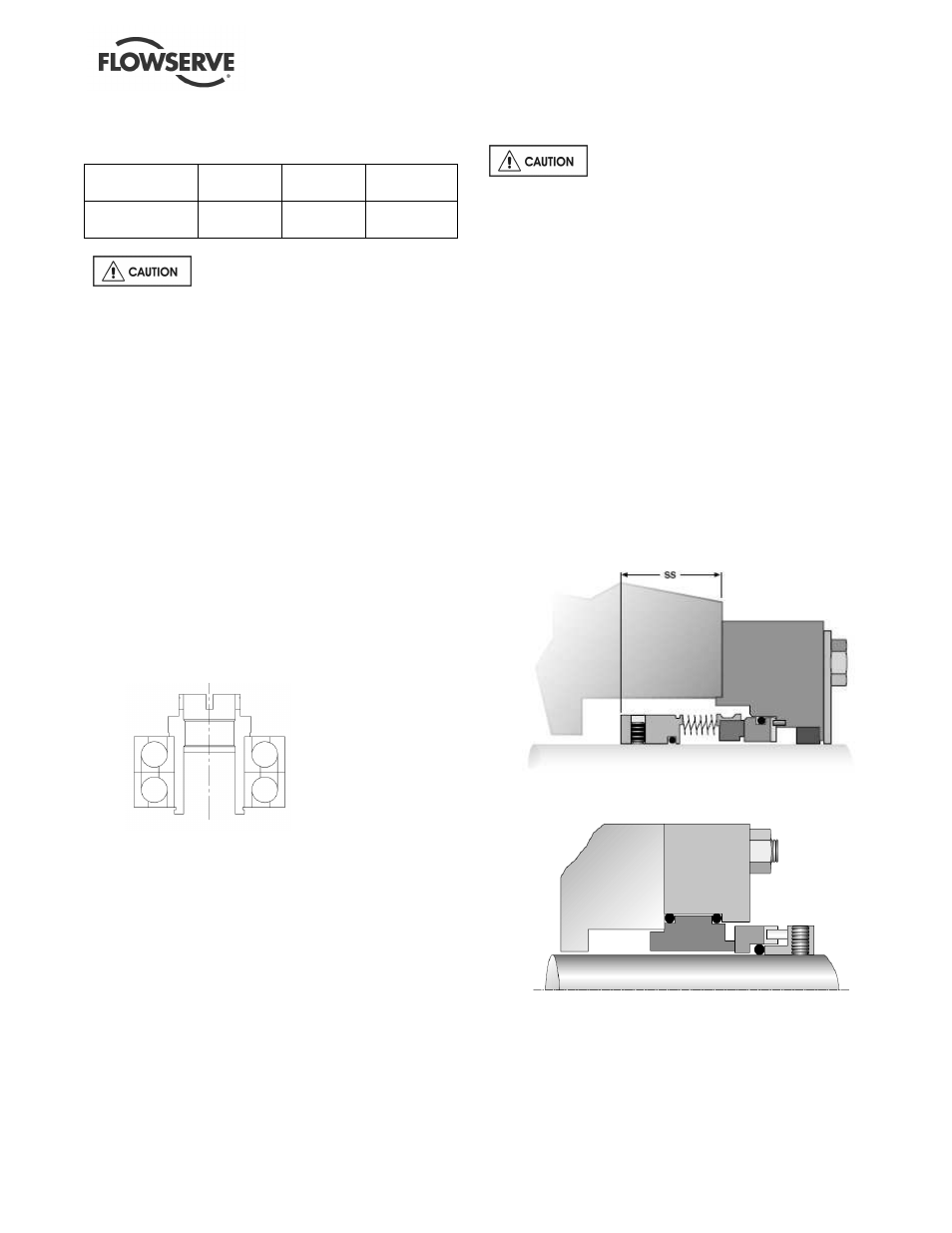
Seal component installation
Component Seal that require setting:
Most component seals required setting. The
impeller must be set and the shaft marked at
box face before seal assembly can take place.
The following steps will build the pump to the
point the impeller can be set and the shaft
marked. The pump must then be disassembled
to the point that the seal can be installed and set
according to the instruction included with the
seal.
Figure 6-11 Typical Inside Component Seal
Figure 6-12 Typical Outside Component Seal