Flowserve ESP3 User Manual
Page 43
ESP3 USER INSTRUCTIONS ENGLISH 26999943 08-11
Page 43 of 64
Always remove the shaft by pulling it
out through the mounting plate end as shaft threads
may cause damage to the line shaft bearings if pulled
through the casing end.
p)
Unbolt and remove the adapter [1340.1].
q)
Unbolt and remove the intermediate columns
[1341.2] and the bearing holders [3250] until the
upper column is reached [1341.1].
r)
The shaft bearings should not be removed from
their housings unless they are to be replaced.
Figure 6.6 shows a listing of allowable bearing
tolerances. If these tolerances are exceeded,
either the bearings [3020.1-.2], shaft [2100], or
bearing holder [3250] should be replaced.
s)
Intermediate shaft bearings [3020.1] can be
pressed or driven out of their bearing holder
[3250] when replacing.
t)
The adapter bearing [3020.2] may be removed
by pressing or driving the bearing sleeve from
the upper flange (column side) out through the
lower end (casing side) of the adapter [1340.1].
u)
Removal of bearings [3031] from adjusting
sleeve [3400]. Remove snap ring [2530.2]. An
arbor or hydraulic press may be used to remove
the bearings from the adjusting sleeve. It is
extremely important to apply even pressure to
the inner bearing race only. Never apply
pressure to the outer race as this exerts excess
load on the balls and causes damage.
Applying pressure to the outer
race could permanently damage the bearings.
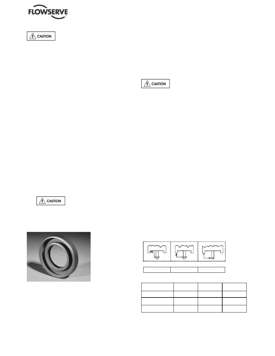
x) If lip seals [4310.1] and [4310.2] (see figure 6-4)
are used, they should be removed and discarded.
Figure 6-4
6.8 Examination of parts
6.8.1 Cleaning/inspection
All parts should now be thoroughly cleaned and
inspected. New bearings, O-rings, gaskets, and lip
seals must be used. Any parts that show wear or
corrosion should be replaced with new genuine
Flowserve parts.
It is important that only non-flammable,
non-contaminated cleaning fluids are used. These
fluids must comply with plant safety and environmental
guidelines.
a)
Inspect impeller [2200] for excessive wear and
etching due to corrosion. Large nicks and deep
pits will unbalance the impeller, cause vibration,
and wear in other parts of the pump. Be sure the
O-ring [4590.2] sealing surface and impeller
threads are clean.
b)
Check pump shaft [2100] for straightness.
c)
Inspect the surface of the shaft in the bearing
[3020.1-.2] areas to make sure it is smooth. It
must be free of grooves, scratches, corrosion or
wear.
d)
Check ends of shaft for burrs. Make sure that
shaft threads are clean.
e)
Inspect the casing [1100] thoroughly, removing
all burrs and foreign matter. Check hydraulic
passages for cleanliness.
f)
Check all other parts for burrs, wear, damage or
corrosion.
g)
Use a dial indicator to check the straightness of
the shaft extension of the driver and check
indicator readings against the values given in
Figure 6-6. Should any of these limits be
exceeded, check with the driver manufacturer
for recommended repair or replacement parts.
Figure 6-5 Motor tolerances
A
B
C
T.I.R. Dimensions -- mm (in.)
Frame Size
A
B
C
143-256TCV
0.10 (0.004)
0.10 (0.004)
0.05 (0.002)
284-286TSCV
0.10 (0.004)
0.10 (0.004)
0.08 (0.003)
324-445TSCV
0.18 (0.007)
0.18 (0.007)
0.08 (0.003)