Flowserve ESP3 User Manual
Page 42
ESP3 USER INSTRUCTIONS ENGLISH 26999943 08-11
Page 42 of 64
b)
Remove bearing lubrication lines [3840.1].
c)
Unbolt and remove the pump casing [1100].
The cove plate [1220] may only
be held in place by the casing and could fall
when the casing is removed.
If applicable, remove the two cap screws
[6570.16] which attach the rear cover [1220] to
the adapter. Carefully remove this part. The
strainer [6531] does not need to be removed
from the casing unless it is to be cleaned or
replaced.
d)
Remove the impeller [2200] by unscrewing it
counterclockwise. See section 6.6.2 for
instructions.
Do not apply heat to the impeller. If liquid is
entrapped in the hub, an explosion could occur.
e)
Remove the shaft sleeve [2400]
f)
Remove the support head [3160].
Pumps without Vapor Proof or Pressurized
Construction
For groups 1 and 2 the support head will be
disconnected from the mounting plate [6130].
For group 3 the support head will be
disconnected from the upper column [1341.1].
For Group 3 pumps, any columns
still attached to the pump at this time must be
firmly supported. The upper column will
disconnect from the mounting plate at the same
time that the support head is disconnected.
Pumps with Vapor Proof or Pressurized
Construction:
remove the support head [3160] from the
bearing bracket [4310.2]
g)
Remove coupling hub.
h)
Pumps with Vapor Proof or Pressurized
Construction:
If a cartridge type mechanical seal [4200] is
used, the spacing clips or tabs should be
installed prior to loosening the setscrews which
attaches the seal to the shaft. This will ensure
that the proper seal compression is maintained.
It will also help prevent damage to the seal in
the following steps.
i)
Unbolt and remove the bearing body [3110]
j)
Remove the retaining ring [2530.2] and key
[6700.3] from the adjusting sleeve [3400].
k)
Holding the shaft [2100] steady, turn the
adjusting sleeve [3400] counterclockwise to
remove the assembly from the shaft
l)
Remove the bearing bracket [4310.2] for pump
with Vapor Proof or Pressurized Construction
only.
For groups 1 and 2 the bearing bracket will be
disconnected from the mounting plate [6130]
For group 3 the bearing bracket will be
disconnected from the upper column [1341.1].
For Group 3 pumps, any columns still
attached to the pump at this time must be firmly
supported. The upper column will disconnect from
the mounting plate at the same time that the bearing
bracket is disconnected.
Before the next procedure, be sure to
cover the shaft threads with a Teflon tape for
protection when sliding parts off the shaft to prevent
the shaft threads from being damaged or causing
damage to other parts.
m) Pumps with Vapor Proof or Pressurized
Construction only.
Unbolt the gland [4120.1 or 4120.3] and
carefully slide it off the end of the shaft. If the
pump contains a seal, VERY CAREFULLY, slide
the seal off of the shaft. Remove all seal
components and discard all O-rings and
gaskets. If the pump contains packing remove
the packing at this time.
n)
Now the stuffing box [4110] can be unbolted and
removed gently from the shaft.
o)
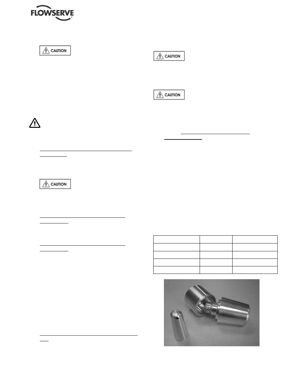
A shaft-nose cone (See Figure 6-3) is
recommended, but not required, for the next
step. If a shaft nose cone is to be used, attach
the cone in place of the impeller [2200]. Remove
the shaft [2100] from the remainder of the pump.
Figure 6-3 Shaft Nose Cones
Description
Dwg #
PCN
GP1 Shaft
BY60723A
75658104
GP2 Shaft
BY60724A
75658112
GP3-13" (2 piece)
BY60901A
75658120
GP3
BY60725A
75658138