Packing information – Flowserve ESP3 User Manual
Page 49
ESP3 USER INSTRUCTIONS ENGLISH 26999943 08-11
Page 49 of 64
Component Seals that do not require setting:
Most double component seals do not required
any settings. The seal may be installed at this
point according to the instructions provided with
the seal. Care must be taken that the seal rotor
is lubricated properly so that it will be able to
move on the shaft as the impeller is set in the
following steps.
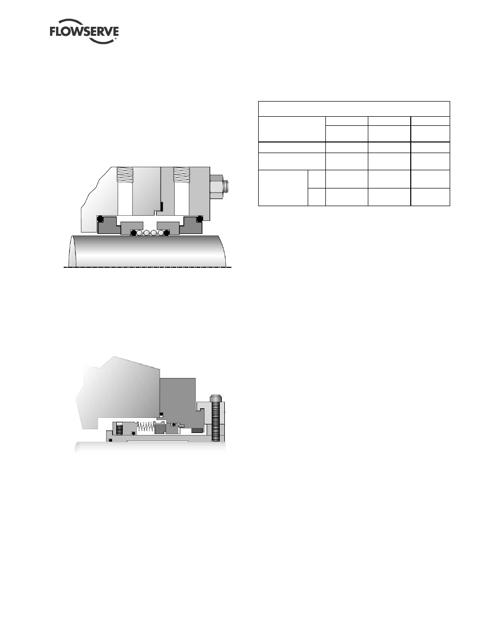
Figure 6-13 Typical Double Component Seal
Cartridge and Gas Canister seal:
CAREFULLY slip the seal [4200] onto the shaft
[2100] and slide it down until it sets into the
stuffing box [4110] or upper column [1341.1] on
with Gas Canister type seals. DO NOT SET
THE SEAL AT THIS TIME. Leave the gland
nuts slightly loose.
Figure 6-14 Typical Cartridge Seal
Packing:
Install one ring at a time, pushing it well into
place. Two rings of packing must be installed,
the seal cage, then succeeding rings of packing
until the box is filled.
NOTE: The joints of succeeding rings must be
staggered. The taped hole in the stuffing box for
packing lubrication must line up with the seal
cage when the packing is compressed.
After the last ring of packing is in place, draw up
the nuts [6580.8] on the gland [4120.1] evenly
finger tight. Save additional packing rings as
they may become necessary as the packing is
tightened during operation.
Figure 6-15
Packing Information
Group 1
Group 2
Group 3
Packing size, square
7.9 mm
(0.31 in.)
7.9 mm (0.31
in.)
9.5 mm
(0.38 in.)
Packing arrangement
2-C-3
2-C-3
2-C-3
Seal Cage width
12.7 mm
(0.50 in.)
19.0 mm
(0.75 in.)
12.7 mm
(0.50 in.)
Max.
28.58 mm
(1.125 in.)
38.10 mm
(1.500 in.)
47.63 mm
(1.875 in.)
Shaft Diameter
Min,
28.52 mm
(1.123 in.)
38. 05 m m
(1. 49 8 in. )
47.57 mm
(1.873 in.)
c)
GP1 and 2 Pumps:
The lower lip seal [4310.2] should be installed
with the spring down into the bearing bracket
[3130]. Fill the cavity between the lips ½ to
⅔
full with bearing grease. Install the bearing
bracket [3130] to the mounting plate [6130]
GP3 Pumps:
The bearing bracket [3130] has already been
installed. The lower lip seal [4310.2] should be
installed with the spring down into the bearing
adapter plate [1340.4]. Fill the cavity between
the lips ½ to
⅔
full with bearing grease. Install
the bearing adapter plate [1340.4] onto the top
of the bearing bracket [3130]. Temporarily hold
the adapter bracket in place with cap screws.
d)
Install bearing/adjusting sleeve assembly.
Screw the adjusting sleeve [3400] to the shaft
e)
Install O-ring [4590.2] and the bearing body
[3110]. Secure with cap screws [6570.9].
The bearing body contains lip seal [4310.1].
The seal is installed with the spring down.
Lubricate the lip seal with grease prior to placing
over the shaft. Fill the cavity between the lips ½
to
⅔
full.
f)
Set the impeller as described in section 6.6.3
g)
Set the seal.
Cartridge and Gas Canister seal:
Follow the instructions provided with the seal.
Tighten the gland nuts [6580.8]. Tighten the
seal sets screws to the shaft. Remove the seal
setting clips.
Packing:
Ensure the gland nuts [6580.8] are evenly finger
tight and then tighten and additional ¼ turn.
Final tightness is set via leakage. A slight
amount of leakage through the gland [4120.1] is
necessary for proper lubrication. Packing
glands must never be tightened to the point