Flowserve ESP3 User Manual
Page 46
ESP3 USER INSTRUCTIONS ENGLISH 26999943 08-11
Page 46 of 64
6.9 Assembly of pump and seal
It is important that all pipe threads be
sealed properly. PTFE tape provides a very reliable
seal over a wide range of fluids, but it has a serious
shortcoming if not installed properly. If, during
application to the threads, the tape is wrapped over the
end of the male thread, strings of the tape will be
formed when threaded into the female fitting. These
strings can then tear away and lodge in the piping
system.
If this occurs in the seal flush system, small orifices can
become blocked effectively shutting off flow. For this
reason, Flowserve does not recommend the use of
PTFE tape as a thread sealant.
Flowserve has investigated and tested alternate
sealants and has identified two that provide an
effective seal, have the same chemical resistance as
the tape, and will not plug flush systems. These are
La-co Slic-Tite and Bakerseal. Both products contain
finely ground PTFE particles in an oil-based carrier.
They are supplied in a paste form which is brushed
onto the male pipe threads. Flowserve recommends
using one of these paste sealants.
Full thread length engagement is required for all
fasteners.
Refer to figure 6-2 for recommended bolt
torques.
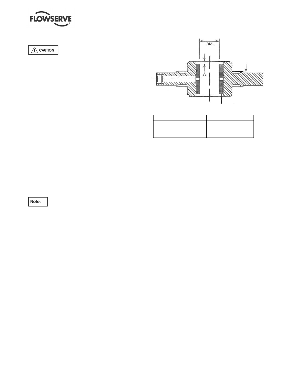
6.9.1 Replacing shaft sleeve bearings
a)
After removing the old intermediate bearings
[3020.1] (see section 6.7.2) clean and deburr
bearing holder bore and lubrication port. Apply a
light coating of grease or oil to bearing holder
bore and out-side diameter of new bearing.
Carefully press new bearing into holder to "A"
dimension in
Figure 6-8.
b)
After removing the adapter bearing [3020.2] (see
section 6.7.2) clean and deburr adapter bore and
lubrication port. Apply a light coating of grease or
oil to bearing holder bore and outside diameters
of new bearings. Carefully press the new bearing
into the adapter flush with the counter bore as shown
in Figure 6-9.
c)
Be sure that all bearings [3020.1-.2] are now
within their bearing holders [3250, 1340.1].
Figure 6-8 Intermediate bearing
Shaft Diameter
A
28.58 mm (1.125 in.)
3.2 mm (.125 in.)
38.10 mm (1.500 in.)
3.2 mm (.125 in.)
53.98 mm (2.125 in.)
3.2 mm (.125 in.)
SHAFT
Holder
Bearing