Flowserve Guardian Sealless Metallic User Manual
Page 13
GUARDIAN USER INSTRUCTIONS ENGLISH 71569212 08-11
Page 13 of 68
flowserve.com
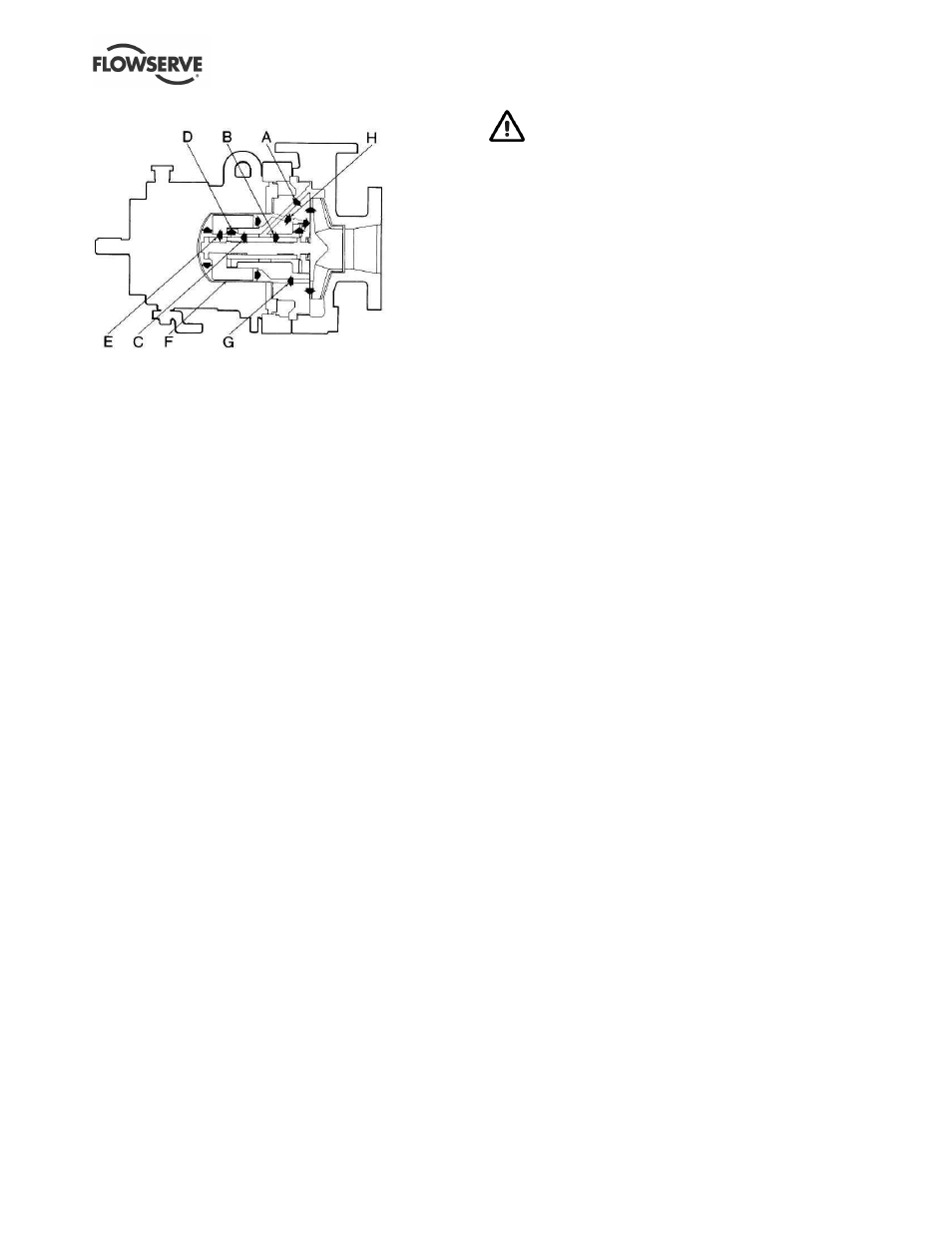
Figure 3-5: Lubrication and cooling path
3.3.5
Power end bearings and lubrication
Ball bearings are fitted as standard on long-coupled
pumps and may be either oil or grease lubricated.
Close coupled pumps utilize the motor bearings for
support of the outer magnet.
3.3.6
Bearing housing
Large oil bath reservoir. (Long-coupled pumps only.)
3.3.7
Driver
The driver is normally an electric motor. Different drive
configurations may be fitted such as internal combustion
engines, turbines, hydraulic motors etc driving via
couplings, belts, gearboxes, drive shafts etc.
3.3.8
Accessories
Accessories may be fitted when specified by the
customer.
3.4 Performance and operation limits
This product has been selected to meet the
specification of your purchase order see section 1.5.
The following data is included as additional
information to help with your installation. It is typical,
and factors such as liquid being pumped,
temperature, and material of construction may
influence this data. If required, a definitive statement
for your application can be obtained from Flowserve.
3.4.1
General temperature limits
See Figures 3-6 and 3-7 for general temperature
limits for Guardian G & H series pumps.
3.4.2
Pressure-temperature ratings
The pressure-temperature ratings for Guardian G & H
series pumps are shown in Figures 3-9A and 3-9B.
To determine which casing material group to
reference, identify the appropriate casing “Material
Group No.” in Figure 3-8. Interpolation may be used
to find the pressure rating for a specific temperature.
The maximum discharge pressure must be less
than or equal to the P-T rating. Discharge pressure
may be approximated by adding the suction pressure
and the differential head developed by the pump.
The suction pressure limit for Guardian G & H series
pumps is limited by the P-T rating.
Example. The pressure temperature rating for a
Guardian pump with Class 300 flanges and CF8M
construction at an operating temperature of 149 ˚C is
found as follows:
a) From Figure 3-8, the correct material group for
CF8M is 2.2.
b) From Figure 3-9B, the pressure-temperature
rating is 21.5 bar.
3.4.3
Alloy cross reference chart
Figure 3-8 is the alloy cross-reference chart for all
Guardian G & H series pumps.
3.4.4
Minimum continuous flow
The minimum continuous flow (MCF) is based on a
percentage of the best efficiency point (BEP). Figure
3-10 identifies the MCF for all G & H series Guardian
pumps.
3.4.5
Minimum suction pipe submergence
The minimum submergence for Unitized self-priming
pumps is shown in Figure 3-11 and 3-12.