Flowserve Guardian Sealless Metallic User Manual
Page 38
GUARDIAN USER INSTRUCTIONS ENGLISH 71569212 08-11
Page 38 of 68
flowserve.com
difference. This number is the thickness of shims
that are required to adjust the impeller.
For example, if the initial measurement between the
closest impeller vane and the bearing holder face is
0.75 mm (0.030 in.), and the thickness of the shims
already inserted is 1.00 mm (0.040 in.), use
1.00 mm – 0.75 mm = 0.25 mm
(0.040 in. – 0.030 in. = 0.010 in.)
Next, add 0.45 mm (0.018 in.) to 0.25 mm
(0.010 in.) to determine the thickness of the
shims required to adjust the impeller properly.
0.25 mm + 0.45 mm = 0.70 mm
(0.010 in. + 0.018 in. = 0.028 in.)
A combination of shims equal to 0.70 mm
(0.028 in.) thickness would then be required to
set the impeller properly.
d) Set the assembly back to horizontal. Remove
the impeller and the 1.00 mm (0.040 in.)
combination of shims from the pump shaft.
Removal should only require using your hands
since the impeller was only hand tightened. If
necessary, use the Durco impeller wrench to hold
the shaft stationary.
e) Place the required number of shims against the
shoulder in the thrust collar [3610] or thrust collar
ring [207]. Thread the impeller back onto the pump
shaft and tighten as described in step 1. Make sure
the shims sit flat between mating faces.
f) Recheck the impeller clearance as described in
step b). If the distance is more or less than
required, repeat steps c) through f) until
clearance is correct.
g) When the clearance is properly set, set the
assembly back to horizontal. Remove the
impeller and thrust collar [3610].
Group 1. Place the thrust collar/pump shaft O-ring
[4610.4] in the groove on the back side of the thrust
collar. Stretch the thrust collar ring/O-ring [4610.5]
over the hub on the backside of the impeller.
Group 2. Remove the thrust collar ring and shims
from the thrust collar. Place the thrust collar/ring
O-ring [4610.5] into the O-ring groove on the
shimming side of the thrust collar. Using an arbor
press, press the thrust collar ring and shims into
the thrust collar. In order to keep the shims from
falling out of the thrust collar during this press, the
ring should be placed on the work surface with the
thrust collar on top of it. Place the thrust
collar/pump shaft O-ring [4610.4] into the groove
on the pump shaft side of the thrust collar. Place
the thrust collar into the bearing holder [3830] so
the thrust journal sits flat on the grooved portion of
the T-shaped bushing [3300.1].
h) Install new impeller gasket (4590.2) and tighten
the impeller until it is firmly seated.
Failure to tighten the impeller
sufficiently may allow liquid to reach the impeller
thread. Additionally, a loose impeller will be
tightened when the pump is started, but may be
very difficult to remove later.
The impeller will be difficult to turn
because there is deformation of the O-rings
during seating of the impeller.
6.7 Disassembly
a) Before performing any maintenance, disconnect the
driver from its power supply and lock it off line.
Lock out power to driver to prevent
personal injury.
b) Close the discharge and suction valves, and
drain all liquid from the pump.
c) Close all valves on auxiliary equipment and
piping, then disconnect all auxiliary piping.
d) Decontaminate the pump as necessary.
If Flowserve Guardian G & H
series pumps contain dangerous chemicals, it is
important to follow plant safety guidelines to
avoid personal injury or death.
6.7.1
Power end removal without breaking
process containment
At this point, it may be necessary to detach some of
the instrumentation.
By following the steps in sections 6.7.1.1 or
6.7.1.2, the process fluid is contained and the power
end can be completely removed. This procedure
does not preclude the use of personal protective
gear. Personnel should follow their standard plant
safety practices.
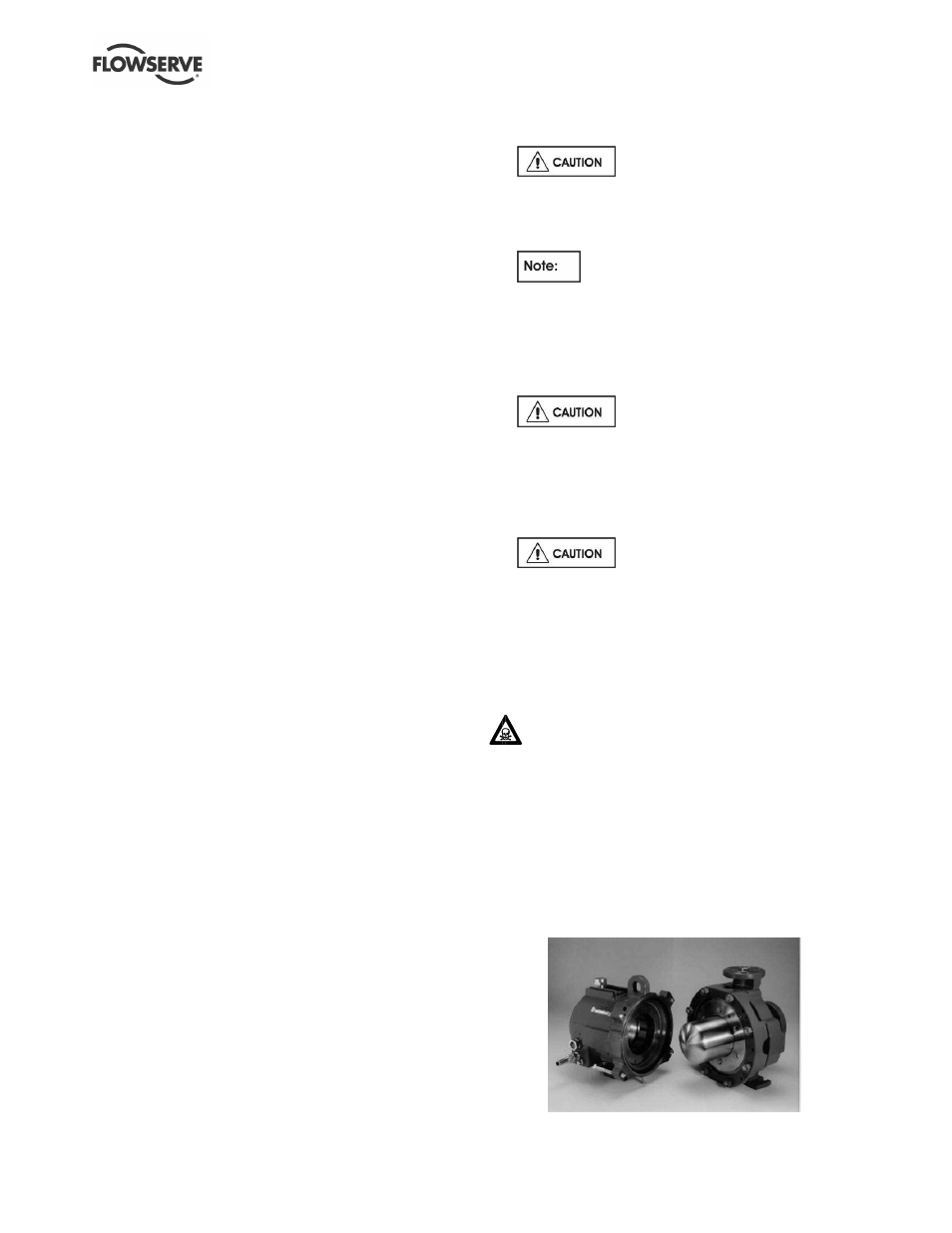
6.7.1.1
Long-coupled Guardian G & H series
pumps
Figure 6-3A: Power end removal with process
contained by wet end