Flowserve Guardian Sealless Metallic User Manual
Page 39
GUARDIAN USER INSTRUCTIONS ENGLISH 71569212 08-11
Page 39 of 68
flowserve.com
a) Remove coupling guard.
b) Remove the spacer coupling.
c) Loosen the cap screw(s) holding the bearing
housing foot to the baseplate.
d) To remove the power end from the wet end,
remove the four (4) bearing housing/adapter
fasteners [6570.5]. The magnetic coupling will
remain connected due to the radial and axial
forces of the magnets.
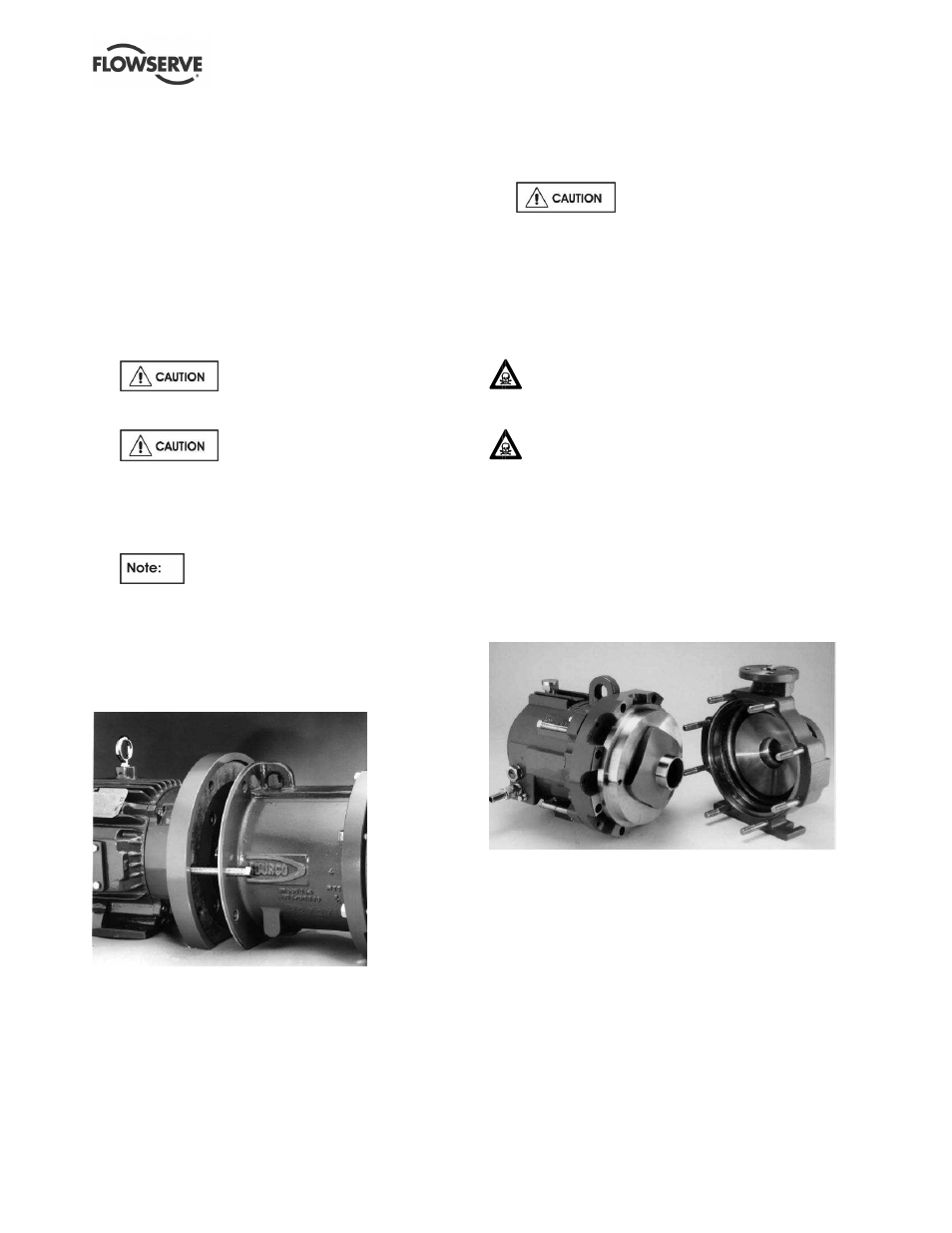
e) Screw the four (4) square head jackbolts [6575] in
the bearing housing through the threaded taps until
each comes into contact with the adapter. Continue
to screw all jackbolts in evenly to detach the wet
end from the power end. (Figure 6-3A.)
Do not attempt to remove the
power end by any other method. The magnetic
force can cause severe personal injury.
Be sure to separate the inner and
outer magnet assemblies evenly. Cocking of the
two can result in serious damage to the magnets
and/or containment shell. It is best to alternatively
give each bolt a turn to ensure proper and even
separation.
Depending on pump size and magnet
length, it may be necessary to move the motor to
complete step e).
f) To disassemble the power end, follow steps a)
through g) in Section 6.7.5.
6.7.1.2
Close-coupled Guardian G & H series
pumps
Figure 6-3B
a) Loosen the fasteners (if applicable) holding the
motor to the baseplate.
b) Remove the four (4) fasteners [6570.10] that hold
the motor flange [251] to the lantern [3132].
c) Engage the two (2) square head jackscrews [6575]
that are located at the 3 o’clock and 9 o’clock
positions on the lantern [3132] until each jackscrew
comes in contact with the motor flange [251].
Continue to screw both jackscrews evenly to
disengage the motor from the wet end of the pump.
(See Figure 6-3B.) It is best to alternate from one
jackscrew to the other to ensure even separation.
Do not attempt to remove the
motor/outer magnet assembly from the wet end
by any other method. The magnetic force can
cause severe personal injury.
d) To complete the disassembly of the close-
coupled drive end, see Section 6.7.5.2.
6.7.2
Removing the entire pump assembly from
the casing
Small amounts of liquid may be trapped in the
casing and/or containment area. Proper
decontamination is the responsibility of the user.
Drain and flush the pump before proceeding to
Sections 6.7.2.1 or 6.7.2.2. The Guardian Magnetic
Drive pump is designed to handle corrosive, toxic,
and hazardous process fluids and may need to be
decontaminated prior to any disassembly.
6.7.2.1
Long-coupled Guardian G & H series
pumps
Figure 6-4: Removing entire pump assembly from
casing
a) Remove the spacer from the spacer coupling.
b) For the larger pumps, attach lifting equipment to
the pump. Place the equipment in light tension to
support the pump when it is removed from the
casing.
c) All maintenance can be performed without casing
removal from the piping. To remove the back
pullout pump assembly from the casing, remove
all casing fastener nuts [6580] from the
casing/adapter fasteners [6572]. (Figure 6-4.)
d) Remove the cap screw(s) holding the bearing
housing foot to the baseplate.
e) Move the back pullout pump assembly toward the
motor and rotate the unit out, leaving the casing
in place. (Figure 6-4.)