Flowserve Guardian Sealless Metallic User Manual
Page 44
GUARDIAN USER INSTRUCTIONS ENGLISH 71569212 08-11
Page 44 of 68
flowserve.com
Spin it rapidly in a counterclockwise direction so
that the wrench handle makes a solid impact with
the work surface to the left of the housing. After
several sharp raps, the outer magnet/flange
assembly should be free and easily removed. It
is recommended that the magnet assemblies be
stored in plastic bags to avoid the necessity to
clean later.
The threads are right hand.
d) Remove the three (3) bearing cover fasteners
[6570.3] and bearing cover [3260]. Remove the
bearing cover/bearing housing O-ring [4610.2]
and discard. Pull the drive shaft and bearing
assembly out of the bearing housing in one
straight motion. Avoid cocking the assembly in
the housing. Remove the wavy washer [127A].
(Figure 6-21.)
e) If the pump is provided with oil lip seals, it is
recommended that these items be replaced during
each pump rebuild. Lip seals [4310.1, 4310.2]
can
be removed from the bearing housing using an
arbor press or tapped out using a flat punch.
f) If necessary, remove the bearing housing foot
[3134] by unscrewing the footpiece fastener
[6570.4] from the bearing housing. A shim
[3126.1] may also be present.
g) If the ball bearings [3011, 3013] need to be
replaced, remove the bearings from the drive
shaft. If the bearings are to be replaced and the
drive shaft reused, extra care should be taken so
as not to damage the drive shaft. Remove the
bearings with a bearing puller. Even pressure
should be applied to the inner bearing race only.
It is recommended that the bearings not be
reused if they are removed from the drive shaft.
Keep contaminants out of the
bearing housing and bearings.
h) The power end disassembly is complete.
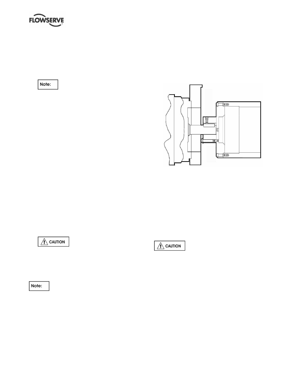
6.7.5.2
Close-coupled Guardian G & H series
pumps – outer magnet/motor
disassembly
This procedure is necessary only if the outer
magnet assembly [230/231] or motor must be replaced.
a) Loosen the set screw the attaches the outer
magnet assembly [230/231] to the motor shaft.
(See Figure 6-22.)
b) Remove the outer magnet assembly [230/231]
from the motor shaft. As a disassembly aide, a
threaded hole has been provided in the center of
the outer magnet flange [231] to enable the outer
magnet flange to be jacked off of the motor shaft.
One of the square head jackscrews [6575] from
the lantern [3132] can be used for this step.
c) Remove the fasteners that attach the outer
magnet flange [231] to the hub [245].
d) To remove the motor flange [251] from the motor,
remove the four (4) motor flange/motor fasteners
[6570.11].
Figure 6-22: Outer magnet/motor assembly
e) Outer magnet/motor disassembly is complete.
6.8 Examination of parts
Cleaning/inspection
Clean all of the parts using a non-flammable solvent
cleaner and inspect them for damage, wear and
corrosion. Replace worn with new genuine
Flowserve parts. Clean all the O-ring grooves
thoroughly and remove any burrs from the grooves.
The pump shaft journal should be carefully inspected.
Particular attention should be given to the impeller
threads, lip seals, magnetic coupling and all bearings.
It is important that only non-flammable,
non-contaminated cleaning fluids are used. These
fluids must comply with plant safety and environmental
guidelines.
Critical measurements and tolerances
To maximize reliability of pumps, it is important that
certain parameters and dimensions are measured
and maintained within specified tolerances. It is
important that all parts be checked. Any parts that do
not conform to the specifications should be replaced
with new Flowserve parts.
Parameters that should be checked by users
Flowserve recommends that the user check the
following measurements and tolerances whenever
pump maintenance is performed. Each of these
measurements is described in more detail on the
following pages.