Flowserve Guardian Sealless Metallic User Manual
Page 50
GUARDIAN USER INSTRUCTIONS ENGLISH 71569212 08-11
Page 50 of 68
flowserve.com
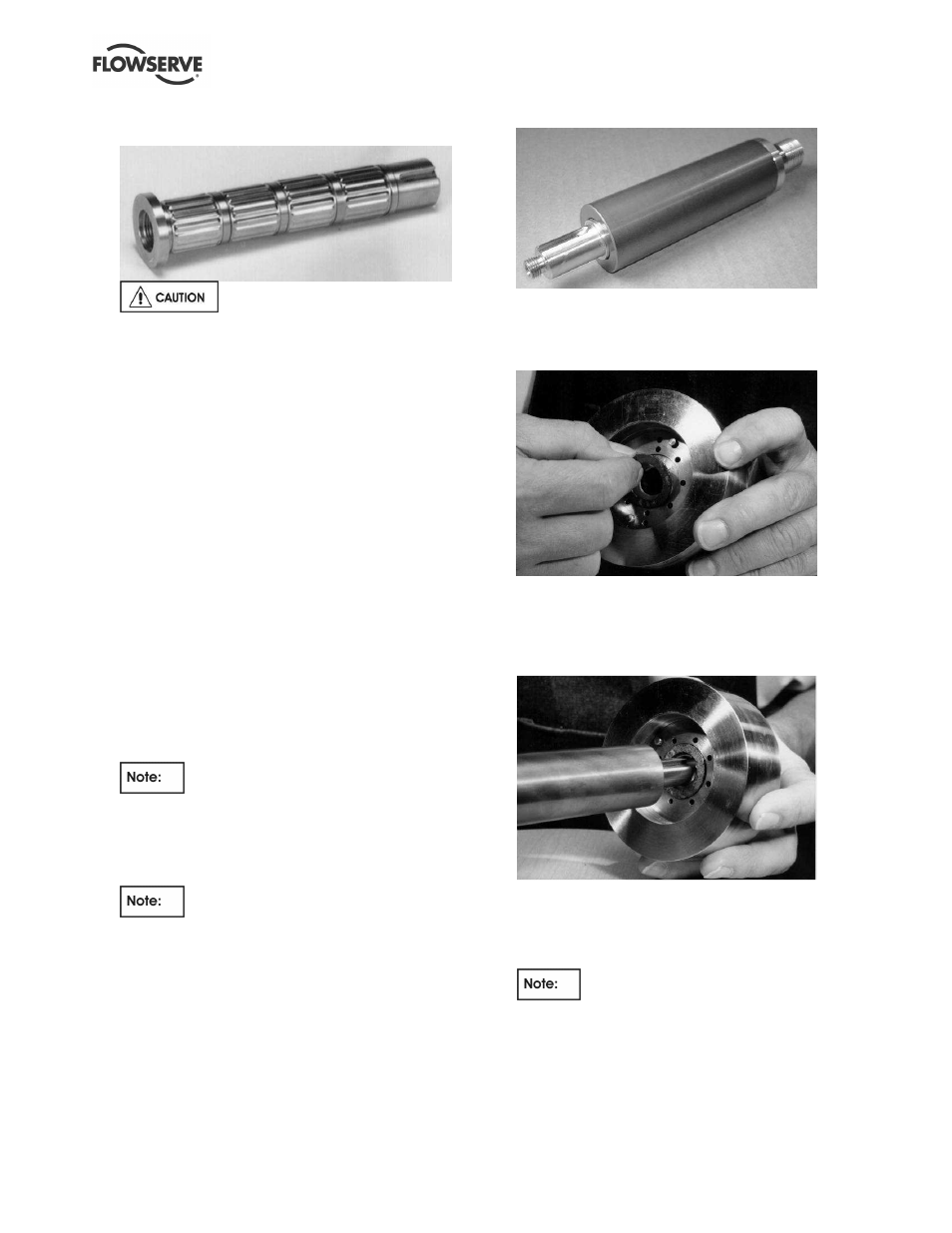
Figure 6-31: Group 2 pump shaft with mounted
tolerance rings
Tolerance rings may have sharp
edges.
l)
Install the pump shaft gasket [4590.6] into the flat
bottomed groove located on the flanged portion
of the pump shaft [2100.1]. Hold it in place with
lubricant. (Figure 6-40.)
m) Using an arbor press, press the pump shaft
journal [213] onto the pump shaft [2100.1] using
the following procedure. DO NOT PRESS ON
THE PUMP SHAFT JOURNAL. PRESS ONLY
ON THE PUMP SHAFT.
First, set the pump shaft journal on a flat surface
below the arbor.
Group 1. The flat surface must have a hole
approximately 0.8-0.9 in. (20-23 mm) in diameter
that is at least 1.5 in. (38 mm) deep.
Group 2. The flat surface must have a hole
approximately 1.4-1.5 in. (36-38 mm) in diameter
that is at least 1.5 in. (38 mm) deep.
Align the pump shaft journal [213] so that the
hole in the flat surface is in the center of the
pump shaft journal bore. Make sure the pump
shaft journal is supported and cannot cock during
the pressing operation.
The flat surface must have a hole in it
to allow the shaft to pass completely through the
pump shaft journal during the pressing operation.
Otherwise, the shaft would bottom out on the
work surface before it is completely pressed
through the pump shaft journal.
An alternate method of pressing the
pump shaft into the pump shaft journal is to use a
bench vise. Make sure the pump shaft and pump
shaft journal are not cocked relative to each other
during the pressing operation.
Second, insert the keyed end of the shaft into the
pump shaft journal. Press the pump shaft through
the journal until the pump shaft gasket butts up
against the pump shaft journal. Make sure the arbor
pressing face is relatively flat so as not to cock the
shaft in the pump shaft journal. (Figure 6-32.)
Figure 6-32: Pump shaft/journal assembly
n) Place a new inner magnet/pump shaft gasket
[4590.6] into the groove on the inner magnet
assembly [220]. (Figure 6-33.).
Figure 6-33: Inner magnet/pump shaft gasket
Slide the pump shaft journal assembly
[213/2100.1] into the inner magnet assembly.
(Figure 6-34.) Insert the pump shaft key [6700.2]
into the key slot of the shaft.
Figure 6-34: Shaft/inner magnet
Place a new cap/inner magnet O-ring [4610.6] in
the O-ring groove in the pump shaft cap [222].
Thread the cap onto the end of the pump shaft to
secure the pump shaft to the inner magnet
assembly. (Figure 6-35.)
Newer Guardian pumps use shaft caps
[222] that have a LEFT HAND thread (i.e. tighten
counter-clockwise). These are indicated by an
“LH” stamped into the end of the cap. Older
pumps that do not have the “LH” marking utilize
right hand threads. All future replacement
shafts/caps will have left hand threads.