Flowserve Guardian Sealless Metallic User Manual
Page 20
GUARDIAN USER INSTRUCTIONS ENGLISH 71569212 08-11
Page 20 of 68
flowserve.com
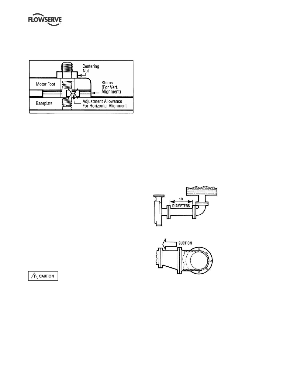
d) The motor feet holes are centered on the motor
mounting fasteners. This is done by using a
centering nut as shown in Figure 4-6.
Figure 4-6: Motor centering fastener
e)
The motor is fastened in place by tightening the
nuts on two diagonal motor mounting studs.
f)
The pump is put onto the baseplate and leveled.
The foot piece under the bearing housing is
adjustable. It is used to level the pump, if
necessary. If an adjustment is necessary, add
or remove shims [3126.1] between the foot piece
and the bearing housing.
g)
The spacer coupling gap is verified.
h)
The parallel and angular vertical alignment is
made by shimming under the motor.
i)
The motor feet holes are again centered on the
motor mounting studs using the centering nut.
At this point the centering nut is removed and
replaced with a standard nut. This gives
maximum potential mobility for the motor to be
horizontally moved during final, field alignment.
All four motor feet are tightened down.
j)
The pump and motor shafts are then aligned
horizontally, both parallel and angular, by
moving the pump to the fixed motor. The pump
feet are tightened down.
k)
Both horizontal and vertical alignment is again
final checked as is the coupling spacer gap.
See section 4.8 for Final Shaft Alignment
4.6 Piping
The protective covers are fitted to both
the suction and discharge flanges of the casing and must
be removed prior to connecting the pump to any pipes.
4.6.1
4.6.1 Suction and discharge piping
All piping must be independently supported,
accurately aligned and preferably connected to the
pump by a short length of flexible piping. The pump
should not have to support the weight of the pipe or
compensate for misalignment. It should be possible
to install suction and discharge bolts through mating
flanges without pulling or prying either of the flanges.
All piping must be tight. Pumps may air-bind if air is
allowed to leak into the piping. If the pump flange(s)
have tapped holes, select flange fasteners with
thread engagement at least equal to the fastener
diameter but that do not bottom out in the tapped
holes before the joint is tight.
4.6.2
Suction piping
To avoid NPSH and suction problems, suction piping
must be at least as large as the pump suction
connection. Never use pipe or fittings on the suction
that are smaller in diameter than the pump suction size.
Figure 4-7 illustrates the ideal piping configuration with a
minimum of 10 pipe diameters between the source and
the pump suction. In most cases, horizontal reducers
should be eccentric and mounted with the flat side up as
shown in Figure 4-8 with a maximum of one pipe size
reduction. Never mount eccentric reducers with the flat
side down. Horizontally mounted concentric reducers
should not be used if there is any possibility of entrained
air in the process fluid. Vertically mounted concentric
reducers are acceptable. In applications where the fluid
is completely deaerated and free of any vapor or
suspended solids, concentric reducers are preferable to
eccentric reducers
Figures 4-7 and Figure 4-8
Avoid the use of throttling valves and strainers in the
suction line. Start up strainers must be removed shortly
before start up. When the pump is installed below the
source of supply, a valve should be installed in the
suction line to isolate the pump and permit pump
inspection and maintenance. However, never place a
valve directly on the suction nozzle of the pump.
Refer to the Durco Pump Engineering Manual and
the Centrifugal Pump IOM Section of the Hydraulic
Institute Standards for additional recommendations
on suction piping. (See section 10.)