Flowserve Guardian Sealless Metallic User Manual
Page 49
GUARDIAN USER INSTRUCTIONS ENGLISH 71569212 08-11
Page 49 of 68
flowserve.com
b) Place the outboard, (T-shaped) bushing [216] in the
outboard end of the bearing holder temporarily
securing it in the same manner as the inboard
bushing.
Special instructions for installing Guardian H
series cartridge type bushings
In some instances Guardian H series cartridge type
bushings can be difficult to install into the bearing
holder due to the tight tolerance between cartridge
sleeve and the bearing holder bore. For these cases,
use the following procedure to install these bushings.
This procedure is only necessary for H
series Guardian pumps with cartridge-type bushings.
For G series Guardian pumps, skip to step i).
c) Heat bearing holder to approximately 71-93 °C
(160-200 °F) with a ball bearing induction heater
or in a clean oven.
Use caution when handling hot
parts. Wear insulated gloves.
d) While the bearing holder is still hot, place the
outboard cartridge bushing into the bearing holder,
seating it fully and engaging the slots of the bushing
with the tabs/pins of the bearing holder. The
bushing should drop freely into the bearing holder.
e) Repeat step d) above with the inboard cartridge
bushing.
f) With the two bushings installed in the bearing
holder, place the shaft/shaft journal assembly into
the outboard bushing, sliding it through the
inboard bushing until it just protrudes from the
other side of the inboard bushing. If the shaft will
not slide through into the inboard bushing,
proceed to step g). Otherwise, proceed to step i).
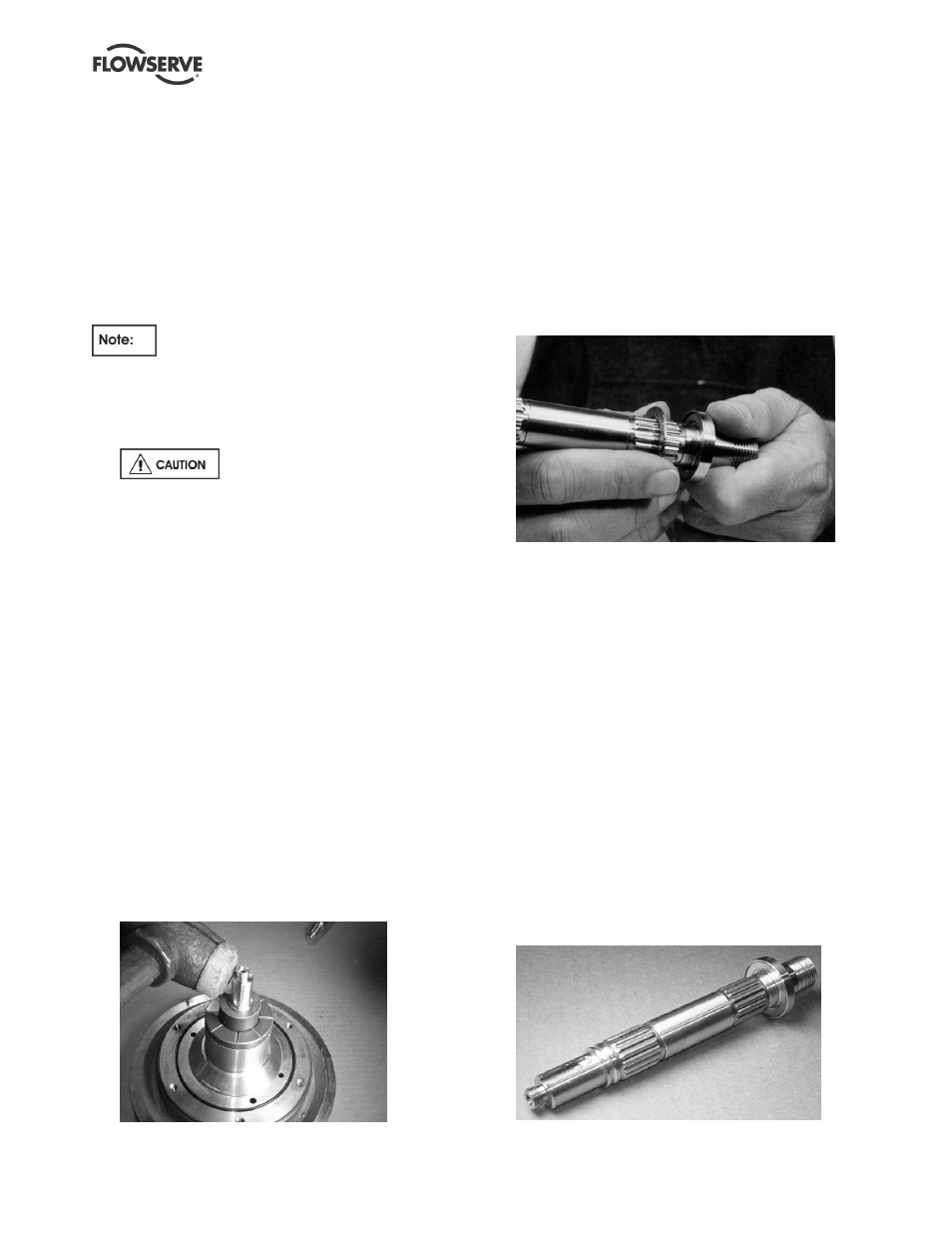
g) With the shaft inserted as far as it will go, use a
soft mallet to
very gently tap around the side of
the keyed end of the shaft/journal from several
directions. (See figure 6-28.) This will help align
the bore of the outboard bushing with the
inboard, allowing the shaft/journal to drop into the
inboard bushing.
Figure 6-28: Guardian H series bushing alignment
technique
h) Rotate the shaft/journal several times to ensure it
spins freely. If it does not, continue to turn the
shaft/journal while
very gently tapping on its side
as in step g). This should fully align the bushings
and the shaft.
i)
Proceed to step j) to complete assembly of the
wet end of the pump.
j)
Place the outboard thrust journal [217] into the
inner magnet assembly. Align the journal with
the locating pins and temporarily secure it in
place with lubricant.
Figure 6-29: Pump shaft with gasket
k) If the pump shaft/pump shaft journal assembly
has been disassembled, follow step k).
Otherwise, proceed to step n). Install the pump
shaft tolerance rings [241] onto the pump shaft.
Do so by first sliding them over the keyed end of
the shaft. Second, expand the tolerance ring in
order to slide it onto the shaft. This can be
accomplished by inserting a screwdriver inside
the ring and prying it open. JUST EXPAND THE
TOLERANCE RING. BE CAREFUL NOT TO
BEND THE TOLERANCE RING. After the
tolerance ring is on the shaft, slide it towards the
impeller end of the shaft until it seats into the
groove closest to the keyed end of the shaft (this
will aid in installing additional tolerance rings).
Perform the same procedure of expanding the
other tolerance ring(s) as the first and slide it
down the shaft. Slide it over the first tolerance
ring and continue until it seats in its respective
groove. (Figure 6-30 and 6-31.)
Figure 6-30: Group 1 pump shaft with mounted
tolerance rings