Flowserve Guardian Sealless Metallic User Manual
Page 52
GUARDIAN USER INSTRUCTIONS ENGLISH 71569212 08-11
Page 52 of 68
flowserve.com
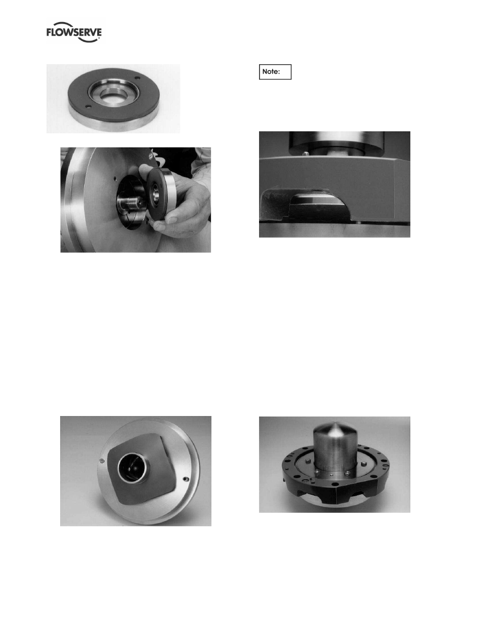
Figure 6-40: Thrust collar
Figure 6-41: Thrust collar
q) Thread the impeller on HAND TIGHT ONLY to
secure the pump shaft and inner magnet
assembly to the bearing holder. (Figure 6-42.)
Do not install impeller gasket [4590.2] and O-ring
[4610.5 and 4610.4] at this time.
Group 1. Make sure that the shims seat flat
between the impeller and the thrust collar when
threading the impeller onto the shaft. If the
impeller rubs the face of the bearing holder
[3830], add more shims in the thrust collar.
Close-coupled pumps ONLY. After reassembly
of the impeller to the pump shaft, the impeller
fastener [2913] and O-ring [4610.8] must be
threaded through the center of the impeller [2200]
into the pump shaft [2100.1]. The impeller
fastener torque should be 34 Nm (25 ft•lbs).
Figure 6-42: Impeller/bearing holder
r) Place the entire wet end assembly vertically on the
workbench with the impeller down and supporting
the weight of the assembly. Adjust the impeller
clearance as described in Section 6.9.4.
s) Install adapter [1340] to bearing holder [3830].
Orientation of the adapter to the bearing
holder is vital for the proper operation of the pump
(venting and draining of the containment area).
Therefore, these parts have been pinned to ensure
the proper radial location. (Figure 6-43.)
Figure 6-43: Adapter/bearing holder pin
t)
Group 1. Stretch bearing holder/retainer O-ring
[4610.7] over holder and place in outer notch of
holder.
Group 2. Place the bearing housing/adapter
O-ring [4610.1] and bearing holder/adapter
O-ring [4610.7] into the O-ring grooves on the
inner diameter of the adapter.
u) Put the bearing holder/containment shell O-ring
[4610.3] into the groove on bearing holder [3830].
Making sure the O-ring sits properly in the groove,
place containment shell [224] and retaining ring
[228] onto the assembly. (Figure 6-44.)
v) Secure the assembly with six (6) retainer ring/
bearing holder fasteners [6570.6]. Tighten the bolts
in a diagonally alternating pattern. (Figure 6-44.)
w)
Group 1. Stretch retainer ring/adapter O-ring
[4610.1] over the outer diameter of the retainer
ring [228].
Figure 6-44: Containment shell with retaining ring