Ptb mounting procedure – FSR PTB Series User Manual
Page 3
FSR
PTB Installation Manual [
Page 3 of 6
]
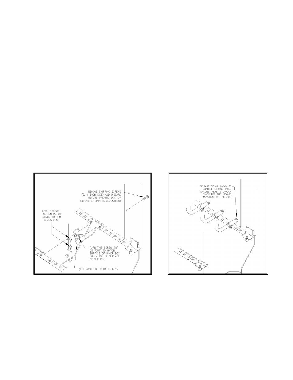
Remove the shipping screws (2) completely and store in a safe place (Fig. 2).
Push down on tabletop box to release and access the connector panel. (Fig 1). The
connector panel chassis will automatically ascend from the outer assembly and expose the
connector plate openings for wiring and mounting the connector plates (not supplied). This
customer-supplied plate must not contain high voltage. This space is designed for CLASS
2 devices only.
Remove the inner box cover side screws (4) (Fig. 1) to allow access to the PTB interior for
wiring.
Cabling is inserted through the cut opening from the bottom of the table and into interior of
the table box. There is a separate compartment with a duplex outlet for 117 VAC service
entry ONLY. Be certain to isolate high and low voltage cabling per local electrical codes.
Allow enough slack in the cable runs to ensure free and full travel of the box while opening
and closing. Use tie-wraps as shown in Fig. 4 to limit strain and pinching. Open and close
the box to confirm adequate clearance.
PTB Mounting Procedure
The PTB series table thickness range is from ¾” to 4”. Adjustments are provided to
accommodate a wide range of table thickness.
Insert the PTB into the table opening and push the housing into the rabbet until the top and
surrounding rim are inside the rabbet. Adjust the four rim height adjustment screws (Fig. 2)
to 1/64” above the table surface. (Final tightening of the locking clamps will pull the table in
later steps)
FIG. 3
FIG. 4