FSR PTB Series User Manual
Page 4
FSR
PTB Installation Manual [
Page 4 of 6
]
The inner box cover, to outer rim height adjustment screws are factory set and should not
require any adjustment. If adjustment does become necessary, loosen the two lock screws
(Fig 3) and turn the adjusting screw to raise and lower the surface of the inner box cover
with respect to the surface of the rim. Retighten the two lock screws (Fig. 3) to secure the
adjustment position.
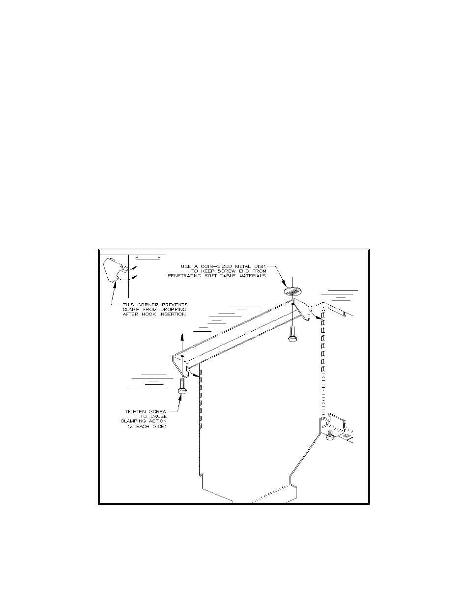
After height adjustments are completed install and tighten the locking clamps (2) as shown
in Fig. 5 to lock the PTB into place.
There is a factory installed duplex outlet provided for local 117 VAC power at the PTB
faceplate. The 8’ AC cord can be plugged into a 117 VAC outlet close to the PTB housing.
The PTB’s power cord is the main-disconnect device. The power socket / outlet should be
installed near the table box and should be easily accessible. The PTB’s are designed to
operate in a maximum recommended ambient temperature (TMRA)
of 45
°
C (113
°
F).
FIG. 5