FSR RGB-144 User Manual
Page 6
LIT1002
CONNECTING THE UNIT
DESCRIPTION OF INPUTS AND OUTPUTS
All video input and output connections are BNC female chassis mount connectors. They will accept a
variety of video input types. The power cord entry accepts the supplied IEC power cordset at 110/220
VAC 50/60 Hz. Typical configuration options are illustrated on the following pages.
Video Input Connections
The video input section on the RGB-144 rear panel provides up to four universal inputs. Each input can
accept composite (NTSC/PAL), s-video, component (RGB, Betacam (Y, Pb, Pr)), and computer video
signals. The connections for each input channel are made via five BNC connectors. Connection points for
each type of video signal are specified below.
Format – RGB
(Typical Devices: Computers)
Format – YUV or Y Pr Pb (Betacam)
(Typical Devices: DVD Player or Betacam Deck)
Source RGB-144
Source RGB-144
R R/CR
Y
G/Y
G G/Y
Pr
R/CR
B B/CB
Pb
B/CB
H
H/C
or
V V
Y
G/Y
U R/CR
Format – S-Video (Y/C)
(Typical Devices: S-Video VCR)
V B/CB
Source RGB-144
Format – Composite/PAL (Typical Devices: NTSC/PAL VCR,
VIDEO CAMERA)
Y
ANY R, G, or B
INPUT
Source RGB-144
C
ANY R, G, or B
INPUT
NTSC/PAL
ANY R, G, or B INPUT
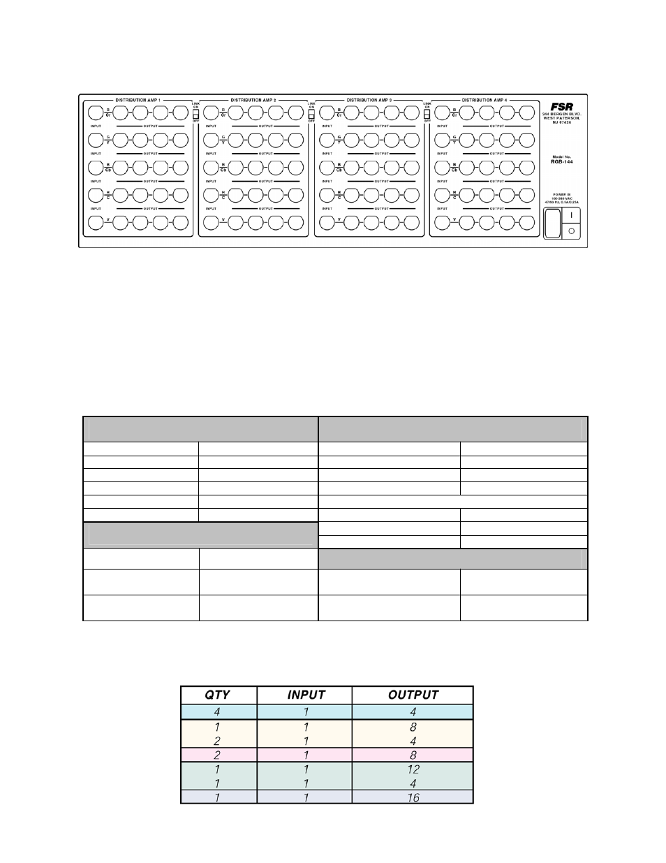
CONFIGURATION CHART
(Matrix showing quantity of input x output combinations for 16 maximum outputs)