Model 256-700 – GAI-Tronics 226-700 Hanset VoIP Telephones with Keypad User Manual
Page 12
P
UB
.
42004-445H
V
O
IP
I
NDUSTRIAL
H
ANDSET
T
ELEPHONES
P
AGE
10 of 24
f:\standard ioms - current release\42004 instr. manuals\42004-445h.doc
02/15
Model 256-700
1. Open the front door and remove the four outer screws from the mid-section. Carefully pull the
enclosure apart until encountering a slight resistance on the left side.
2. Pull on the left side of the enclosure until the hinge plugs pull loose to separate the front and rear
halves. Set the front half of the enclosure aside.
3. There are four mounting holes in the rear enclosure. Mount the enclosure on the wall using four ¼-20
machine screws with nuts and washers or #14 wood screws of appropriate length for the mounting
surface.
4. Drill a hole that is appropriate for the type of bushing that is to be used.
5. Reinsert the hinge pins to attach the front half of the enclosure. Insert the Ethernet cable through the
gland bushing and install the cable as shown in the “Field Wiring Installation” section on page 14.
N
OTE
: Conduit may be used in place of the provided gland bushing. If used, the conduit entrance
must be sealed after the cable is installed.
6. Connect any desired peripheral devices. Refer to page 16 for connection information.
7. Perform the initial programming of the telephone. Refer to the “Programming” section beginning on
page 19.
8. Verify operation by calling to and from another telephone. Verify operation of peripheral equipment.
9. Close the mid-section and tighten the four screws (10–12 in-lbs. of torque recommended).
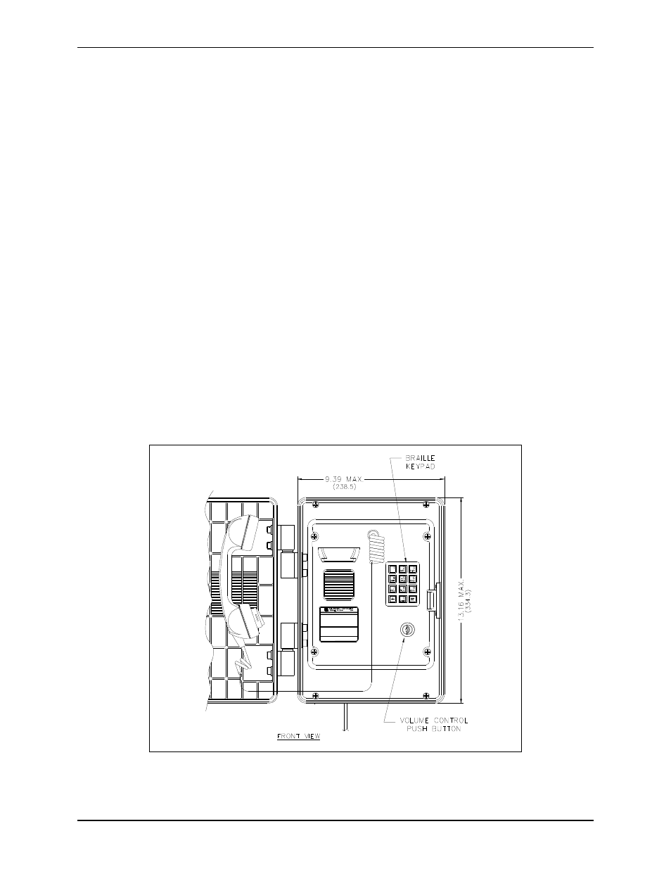
Figure 8. Model 256-700 VoIP Telephone Outline Drawing
(Front door open)