Interfaces, Power, Azi interface – GAI-Tronics 12580-001 Audio Distribution Module User Manual
Page 5
Pub. 42004-600L2C
Model 12580-001 Amplifier Distribution/Monitor Module
Page: 5 of 17
f:\standard ioms - current release\42004 instr. manuals\42004-600l2c.doc
10/11
Interfaces
The Model 12580-001 Amplifier Distribution/Monitor Module provides a number of external interfaces,
all of which are located on the Distribution/Monitor PCBA.
Power
The ADM uses 3-position terminal block TB19 (labeled PWR
IN) to deliver dc power (12 V dc) to the
PCBAs and to provide an earth ground connection for them. Two-position terminal block TB20 (labeled
PWR
OUT) brings out the dc power from TB19, allowing additional Snaptrack
™ modules to receive
power. The pinout for TB19
is shown in Table 1 and the pinout for TB20
is shown in Table 2.
WARNING
Incorrect connection of the power source to TB19 or TB20 may cause damage to this assembly.
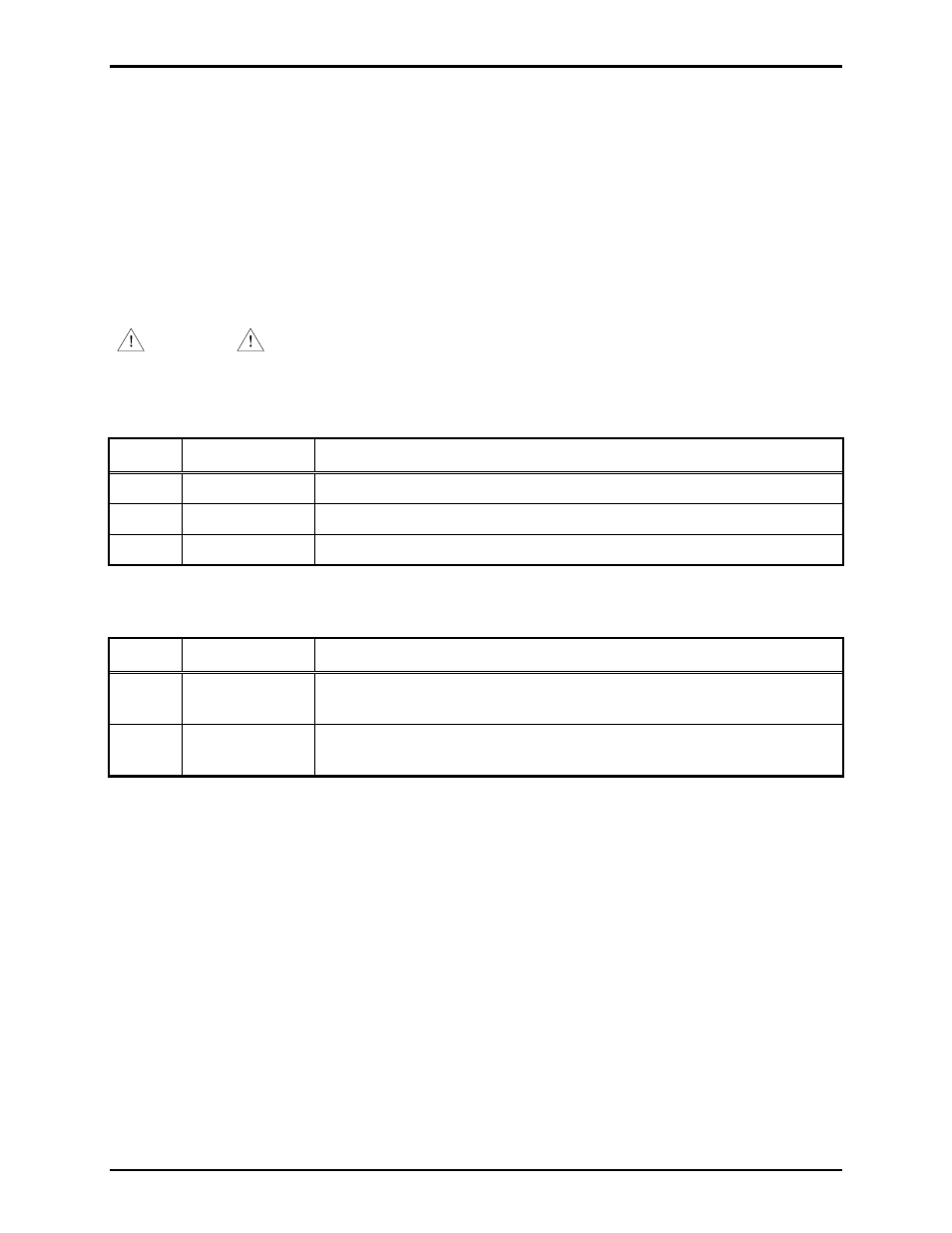
Table 1. Power Input - TB19 Pinout
Pin No.
Function
Description
1
PWR
IN
+
Connects to the positive lead of the power supply (input)
2
PWR
IN
−
Connects to the negative (ground) lead of the power supply (input)
3
PWR
IN
EGND Connects to earth ground (input)
Table 2. Power Output - TB20 Pinout
Pin No.
Function
Description
1
PWR
OUT
+
Connects the positive lead of the power supply to other Snaptrack
™
modules (output)
2
PWR
OUT
−
Connects the negative (ground) lead of the power supply to other
Snaptrack
™ modules (output)
AZI Interface
DB-25 style connector J1 interfaces the Amplifier Zone Interface (AZI) PCBA to the ADM. J1 connects
the six central amplifier input lines, the RS-485 data communication line, and earth ground of the AZI
PCBA to the ADM. The six central amplifier input lines are connected to the following 3-position
terminal blocks: TB2, TB5, TB8, TB11, TB14, and TB17.