GAI-Tronics IPE2500A, IPE2500A-MLS Paging Encoder / Desktop Controller User and Installatoin Manual User Manual
Page 54
Installation
IPE2500A and IPE2500A-MLS Paging Encoder/Desktop Controller
03/12 48
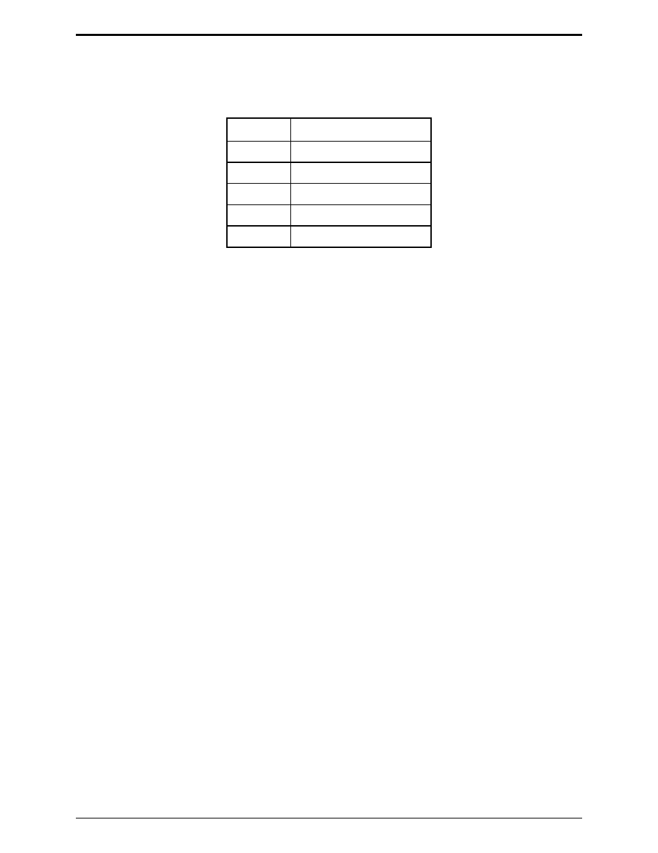
Program the desk set’s line level to the setting that approximates the audio level previously measured.
Refer to the following table for these settings:
Line Output Adjustment Table
Setting
Line Level (600-ohm)
03
−10 dBm
07
−5 dBm
0C 0
dBm
18 +5
dBm
2D +10
dBm
If an RF service monitor is not available, use a portable or mobile radio. Transmit to the station and
measure the nominal voice audio on the desk set telephone line. Set the desk set receive level to the
nearest level that was measured according to the table above.
Line Out Adjust for the IPE2500-MLS
The IPE2500A-MLS allows the adjustment of each of the four available lines. When setting line output
levels for an MLS desk set, follow the same procedure described above but select the appropriate line to
adjust using the programmable buttons: PB1 for line 1, PB2 for line 2, PB3 for line 3 and PB4 for line 4.
Multi-Select Considerations for the IPE2500-MLS
The architecture of the MLS board allows for simultaneous transmission on any of the four available
lines. However, due to the design of the circuit, special considerations regarding line levels and line
termination must be addressed. When a multi-select combination is engaged during transmission, the
actual wire lines are physically connected together. If a line in the multi-selection has line termination
enabled, it is presented as a load to the other lines in the selection during transmission resulting in a
heavier load for the output driver. To provide compensation for this, the line output adjustment includes
an additional setting that instructs the unit to add additional output gain during multi-select transmissions
when lines in the selection have line termination enabled.
By default, line-termination compensation is enabled for all lines of the MLS board. If a parallel unit on
a particular line provides the line termination but does not present a significant transmit load to the desk
set, this compensation can be disabled using the
CTL
+
PB1
,
2
,
3
or
4
combination. When line
termination compensation is enabled, a ‘T’ will be seen to the right of the line out gain during the line out
adjustment.
In addition to line termination compensation during multi-select transmission, the unit must select one
line out gain during a multi-select transmission. In some installations, the line out gain of each line may
not be the same. This allows for proper line level for single channel transmission. However, during a
multi-select transmission, only one gain can be used. The gain used will be the highest gain of any
selected line. Careful consideration during system installation should be observed to try to equalize the
levels if multi-select transmissions are to be used often. High output level settings may result in
distortion of the transmit audio particularly when three to four lines are selected.