GAI-Tronics IPE2500A, IPE2500A-MLS Paging Encoder / Desktop Controller User and Installatoin Manual User Manual
Page 57
IPE2500A and IPE2500A-MLS Paging Encoder/Desktop Controller
Installation
51
03/12
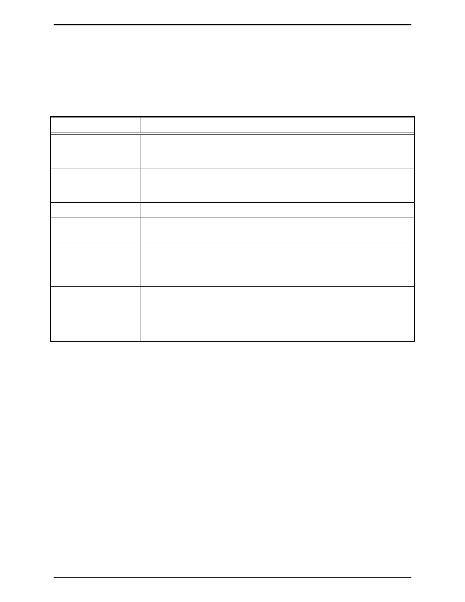
PB2 – DC Module Diagnostics
This function is selected after entering Internal Diagnostics (
PB3
).
DC Module: If the dc module (XDC0001A Kit) is installed, this mode allows the board to be exercised
with both positive and negative currents and sets the DCLOTL. The threshold for DCLOTL is
adjustable, but is factory preset for most installations. The asterisk (*) is present in the lower right corner
if the line voltage is above the preset DCLOTL threshold.
Button(s)
DC Module Diagnostics Mode Function:
VOLUME
Up or
VOLUME
Down
Increases/decreases the dc value sent to the dc module. This value
determines the dc current level and is a hexadecimal number ranging from 00
(lowest current) to 0x3F (highest current).
CTL
+
VOLUME
Up or
CTL
+
VOLUME
Down
Works in the same manner as the function above, but increases or decreases
the value by 10 rather than 1.
TRANSMIT
Exits the dc module diagnostic mode.
MONITOR
Toggles to the polarity of the current being generated. The display shows
+ for positive and − for negative polarity.
CTL
+
PB1
Allows the DCLOTL threshold to be set. In order for this setting to be done
properly, a dc supply must be connected to the line pair with 3 volts. When
CTL
+
PB1
to pressed, the unit reads the dc voltage on the line and saves the
value for future DCLOTL operation.
CTL
+
PB4
Like
CTL
+
PB1,
this key sequence sets the DCLOTL threshold. However,
no dc supply is needed. To set the threshold, set the current out into the
proper line load (typically 8 kilohms) by using the
VOLUME
Up or Down
buttons. When the proper current is reached, press
CTL
+
PB4.
The unit
reads the voltage for future DCLOTL operation.