Gasboy 9800A User Manual
Gasboy Hardware
032114 Rev. 8243
Page 1
MODEL 9800A FRONT LOAD VAPOR RECOVERY KIT INSTALLATION INSTRUCTIONS
This instruction sheet covers the installation of the Model 98A Front Load Balanced System Vapor Recovery Kit. If
you are installing another manufacturer’s vapor recovery system, you may need to modify the nozzle boot using the
Modify Nozzle Boot instructions below. If you ordered a Vapor Recovery Kit, P/N 032107, you should have
received the following:
Item
Qty.
P/N
Description
1
1
032671
Clamp and Reel Assy.
2
1
063816
Support Post
3
1
017930
Cap plug 1-1/2”
4
3
051955
Screw 5/16-18 x 2
5
4
068080
Washer 5/16
6
4
068875
Washer, Lock 5/16
7
1
056924
Spacer
8
1
013250
Bolt 5/16 (Anchor)
9
1
047219
Plug Button
10
1
051970
Screw 5/16-18 x 2-1/2
Item
Qty.
P/N
Description
11
1
064560
¾” Swivel
12
1
038502
Nozzle-Emco VR
13
1
030301
Hose GY 7.5’
14
1
066817
Splitter, Emco
15
1
030407
Hose ¾” HW 1.5’
16
1
017270
¾” to 1” Bushing
17
1
044007
Breakaway
18
1
030303
Hose GY 4.5’
N/A
1
032114
Instruction Sheet
N/A
1
035282
Warning Sheet
Important: Always use a UL-classified gas- and oil-resistant pipe compound on all male pipe threads when
assembling these components. All references to pipe compound in these instructions imply UL-classified pipe
compound.
1.
Read all instructions before beginning. A separate instruction sheet is packed with the EMCO Wheaton splitter
manifold, which is required for mounting this component. Also, read and follow all precautions regarding
remote dispensers and pumps on the Warnings and Safeguards sheet, 035282, included in this kit.
2.
Turn off power to the dispenser at the breaker and activate emergency shutoff valve.
3.
Mount the splitter per the EMCO Wheaton instructions.
Assemble Product Jumper Hose
4.
Assemble ¾” x 1” bushing (017270) to dispenser outlet. Assemble ¾” swivel (064560) to one end of ¾” jumper
hose (030407). Assemble fixed end of jumper hose to bushing on dispenser outlet, and the swivel end at the
splitter port labeled FUEL.
Mounting Hose Retriever
5.
Assemble clamp and reel assembly (item 1) to support post (item 2) with hardware items 4, 5, and 6.
6.
Install reel and support post assembly to side of dispensing unit with items 4, 5, 6, 7, and 10 and leave loose.
Item 7 mounts between post and side panel.
7.
Making sure that support post is plumb, mark and drill a 5/8” dia. x 1-3/4” deep hole in island. Install anchor
bolt (item 8) into island surface. Install items 4, 5, and 6.
8.
Tighten all hardware from Step 9. Plug hole in support post with item
9.
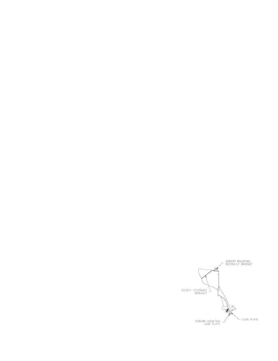
Modifying Nozzle Boot
9. If using a long spout vapor-recovery nozzle, it may be necessary to
remove the nozzle restraint bracket and the lock plate as shown in the
illustration at right.