Gasboy 9800A User Manual
Gasboy Hardware
032119 Rev. 0069
INSTRUCTION SHEET – REPLACING MERCURY SWITCH
(9800A/2600A 215A/7215A FRONT LOAD MODELS)
1. Refer to the Warnings and Safeguards sheet (P/N 035282) included in the kit regarding precautions for the remote
dispensers and pumps.
2.
Remove door from pump/dispenser.
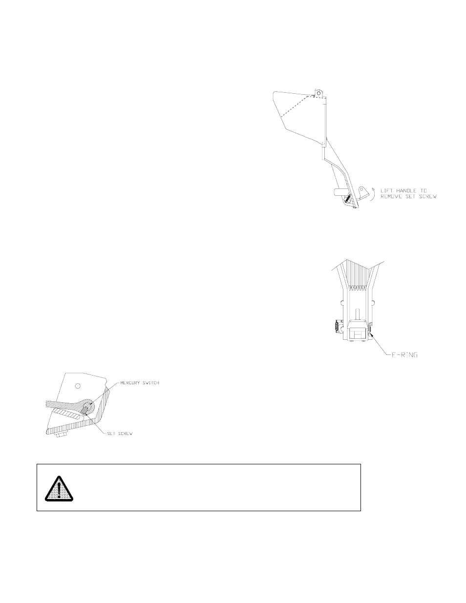
3. Lift handle to access set screw used to secure the mercury
switch (see figure at right).
4. Remove set screw. It may be necessary to loosen thread lock on
set screw using a heat gun. If this is necessary, follow steps 4a –
4d, which describe removal of the nozzle boot assembly so heat
gun may be used a safe distance from the pump, otherwise skip
to step 5.
4a. Disconnect the wire plugs which connect the boot assembly to
the intrinsically safe barrier.
4b. Remove the two bolts which attach the nozzle boot assembly to the pump frame so the boot assembly may be worked
on a safe distance from the pump.
4c. Heat the set screw with a heat gun for approximately 30 seconds, which will allow easy removal of the set screw.
5. Remove the e-ring located on the end of the mercury switch (see figure
at right).
6. Slide mercury switch out.
7. Install replacement mercury switch.
8. Apply a light coat of thread lock to set screw threads
9. It is important that the set screw engages the hole in the shaft of the
mercury switch (see figure below).
10. Reinstall e-ring on the mercury switch.
Do not dispose of or incinerate the mercury switch.
Return the entire switch unit for recycling to:
Power Components
56641 Twin Branch Dr.
Mishawaka, IN 56545