Test 8 — plasma start, Test 9 — torch cap sensor, Powermax1000 – Hypertherm Powermax1000 Service Manual User Manual
Page 59
MAINTENANCE
3-26
powermax1000
Service Manual
1
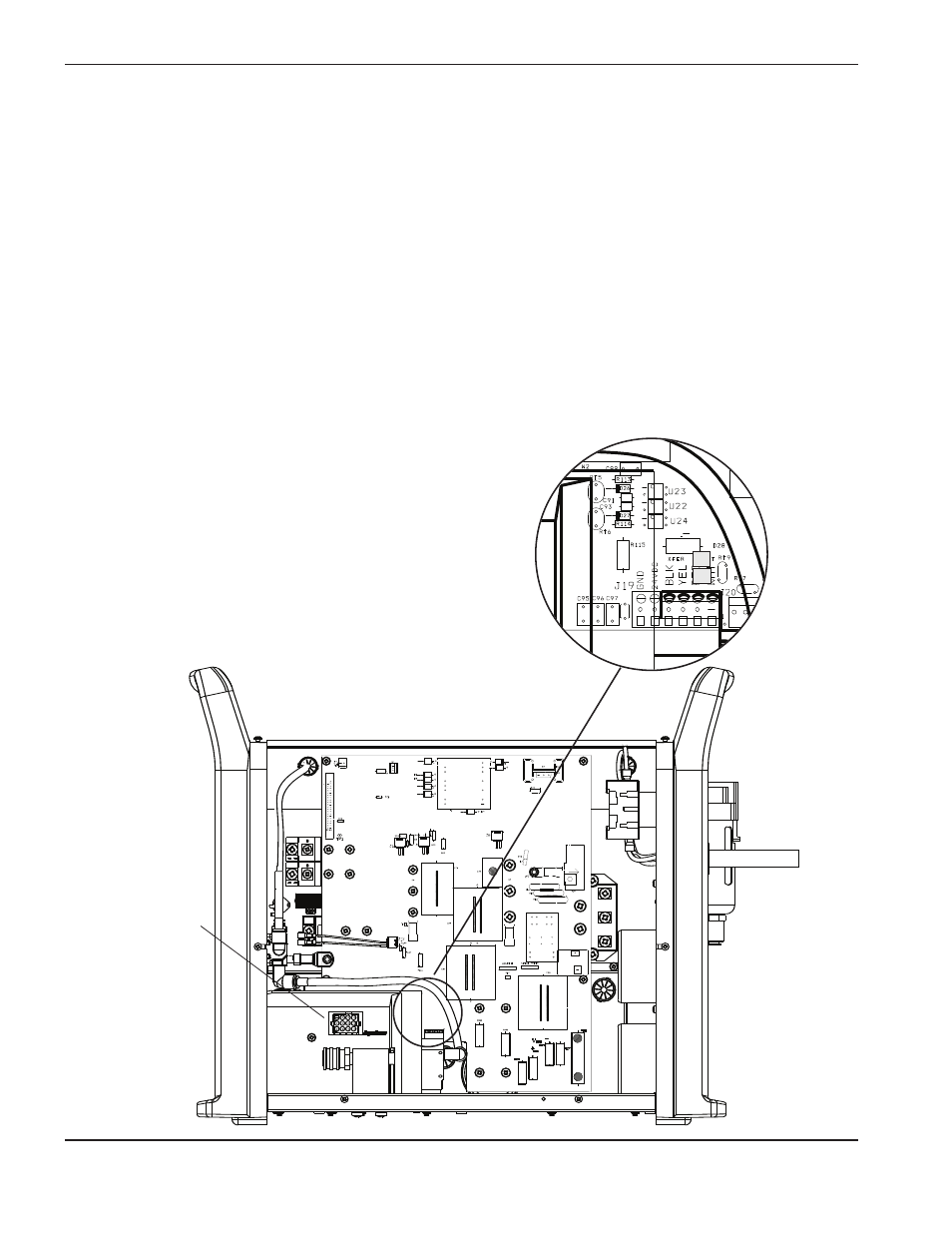
Test 8 – plasma start
• After turning ON the power, put a jumper wire between red and white on the machine interface (J19). The
torch should produce an arc. Note: This only applies to the machine torch.
• If the torch fires, inspect the machine interface cable and verify the start signal from the CNC by verifying
that the START LED on the control board illuminates (see
Control board LEDs).
• If torch does not fire, verify that the Start LED on the control board (PCB3) also is not illuminating.
• To verify hand torch operation, pull the trigger and verify that the Start LED illuminates (see
Control board
LEDs).
• If the Start LED is OFF, verify continuity between the purple and orange wires on the Easy Torch Removal
(ETR) connector of the torch lead.
• If the Start LED is OFF and the trigger works correctly, put a jumper wire between pins 3 and 4 of U22. If
the Start LED illuminates, replace the power board (PCB2). If it does not illuminate, replace the control
board (PCB3).
80
Test 9 – torch cap sensor
• Remove the ETR connector (J18) from the power supply.
• Check the continuity of pins 11 and 12 at the connector
end of the torch with consumables installed in torch.
• If open, check the wiring in the torch leads and cap
sensing switch.
• Put a jumper wire between pins 3 and 4 of U23 with the
power OFF.
• Turn ON the power. If the torch cap sensor LED goes out,
replace the power board (PCB2). If the LED remains
illuminated, replace the control board (PCB3).
ETR connector
(J18)