Infloor Brass Manifold User Manual
Page 3
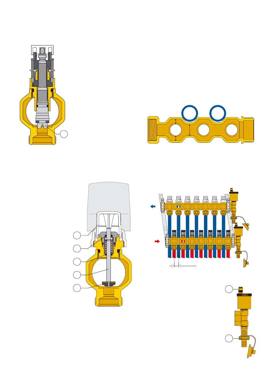
Construction details
Flow manifold
The micrometric regulating valve
obturator is made of plastic (POM)
and features an upside down V
channel (1) to provide greater
precision when regulating the flow
delivered to the floor system circuits.
This solution offers the following
advantages with respect to the
traditional conically shaped
obturator:
- greater precision, particularly for
the low flow rates usually
encountered in this kind of system.
- proportional flow rates due to the
ability to mould the fluid passage
profiles.
- absolute dimensional consistency
during manufacture due to the
die-cast obturator.
Return manifold
The return manifold is equipped with manual shut-off valves (1)
which are used to shut off the flow to individual circuits.
They can also be used with a
thermoelectric actuator
which, when used with an
ambient
thermostat,
maintains the ambient
temperature at the set limits
when thermal load varies.
The obturator stem (2) is
made of polished stainless
steel to minimise friction and
prevent harmful encrustation
from forming.
The control device upper part
features a double EPDM
O-ring seal (3) – (4) on the
sliding stem.
The obturator (5) is made of
EPDM and is moulded to
optimise the hydraulic
characteristics of the valve
and reduce noise to a
minimum as the fluid
passes through and as it
gradually opens and closes
when operating with a
thermo-electric actuator.
Exterior shape of the manifolds and mounting brackets
The exterior of the manifold deserves special mention because it
can be cast in any shape to meet any requirements.
In the example shown below, indentations have been created in the
manifold to correspond to the plastic pipes exiting from the upper
manifold, thus partially accommodating the pipes and reducing
their overall thickness. This does not interfere with the pressure loss
values because the sections with the indentations (a) are equal to
the sections in which the pipes are branched (b) and (c) and where
the regulating parts (micrometric regulating and shut-off valve
obturators) obstruct the passage of the fluid.
The partial accommodation of the pipes in the indentations created
in the manifold is further enhanced by the shape of the mounting
brackets, which are slanted to create a
3/4 in. offset between the
upper and lower manifolds.
As shown in the figure below, this offset positions the pipes so that
they perfectly match the profile of the manifold during installation.
End fitting and automatic air vent valve
The end fitting consists of a fill/drain cock (1)
and an automatic air vent valve with a
hygroscopic safety cap (2). It has been
specifically designed to close the air vent valve
automatically if there is water near the vent
itself.
1
1
3
4
2
5
a
b
c
10
0
8
6
4
2
10
0
8
6
4
2
10
0
8
6
4
2
10
0
8
6
4
2
10
0
8
6
4
2
10
0
8
6
4
2
10
0
8
6
4
2
10
0
8
6
4
2
10
0
8
6
4
2
10
0
8
6
4
2
10
0
8
6
4
2
10
0
8
6
4
2
10
0
8
6
4
2
10
0
8
6
4
2
25 mm
2
1