Specification summaries, 20 δp (kpa) – Infloor Brass Manifold User Manual
Page 7
Pre-assembled distribution manifold for radiant panel systems with 3 (from 3 to 13) outlets. Brass body. EPDM seals. 1” (1” and
1 1/4”) threaded F connections. 3/4"M outlet connections. Medium: water, glycol solutions. Maximum percentage of glycol: 30%.
Maximum working pressure 10 bar. Temperature range 0–80°C. End fitting maximum discharge pressure 2,5 bar.
Consists of:
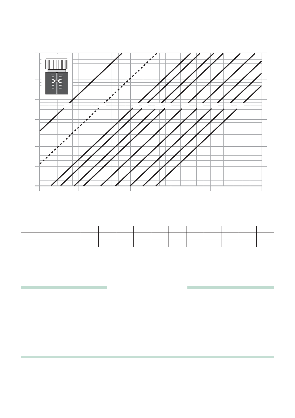
- Flow manifold complete with micrometric preregulating valves with graduated scale from 1 to10. Accuracy ± 5%.
- Return manifold complete with shut-off valves for use with thermo-electric actuator.
- Pair of end fittings consisting of a fitting with automatic air vent and drain cock.
- Pair of shut-off ball valves.
- Pair of mounting brackets.
SPECIFICATION SUMMARIES
20
10
12
14
5000
1000
100
100
G (l/h)
ΔP (mm w.g.)
200
50
500
2000
500
16
18
25
30
35
40
45
50
60
70
80
90
120
140
160
180
200
250
300
350
400
450
900
800
700
600
60
70
80
90
120
140
160
180
250
300
350
400
450
1200
1400
1600
1800
2500
3000
3500
4000
4500
50
10
1
2
0,5
5
9
8
7
6
0,6
0,7
0,8
0,9
1,2
1,4
1,6
1,8
2,5
3
3,5
4
4,5
12
14
16
18
25
30
35
40
45
20
ΔP (kPa)
10
0
8
6
4
2
10
0
8
6
4
2
4
5
6
7
8
9
10
1,5
3
2
1
1
0,06
6
1,5
0,09
9
2
0,18
18
3
0,21
21
4
0,27
27
5
0,31
31
6
0,42
42
7
0,53
53
8
0,7
70
9
0,89
89
10
1,15
115
Adjustment position
Kv
Kv
0,01
Hydraulic characteristics of the micrometric valve
- Kv = flow in m
3
/h for a pressure loss of 1 bar
- Kv
0,01
= flow in l/h for a pressure loss of 1 kPa