Infloor Brass Manifold User Manual
Page 4
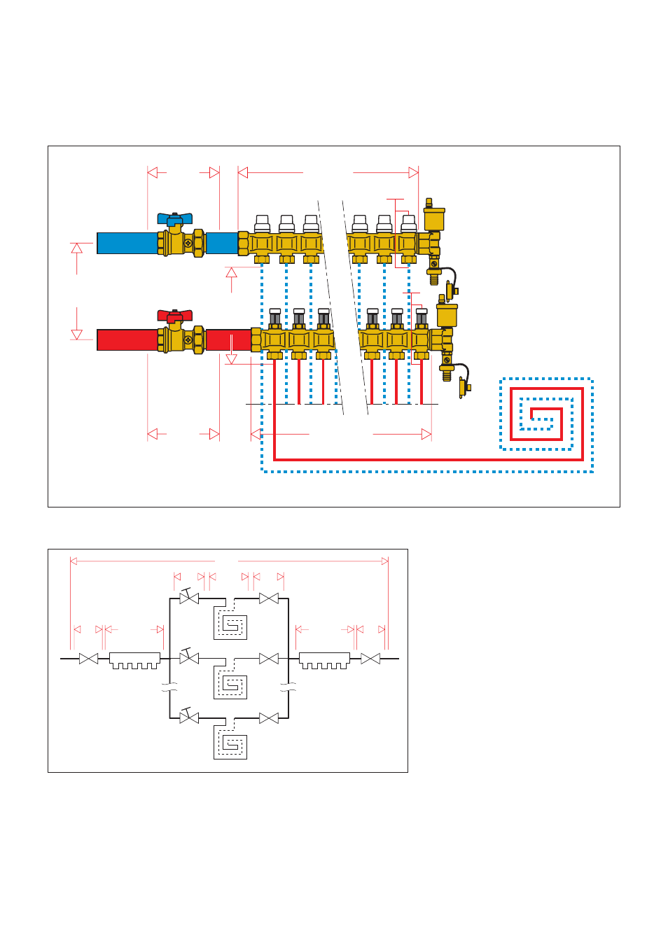
Hydraulic characteristics
To determine the hydraulic characteristics of the circuit, we must calculate the total pressure loss experienced by the flow of fluid as it passes
through the manifold unit parts and the radiant panel circuits.
From a hydraulic standpoint, the manifold unit and circuits can be shown as an assembly of hydraulic elements that are arranged in series and
parallel to each other.
ΔP
Tot
= Total loss at the manifold heads
(Flow + Return + Loop)
ΔP
MV
= Localised loss at the micrometric
regulating valve loop (loop flow)
ΔP
Loop
= Loop loss (loop flow)
ΔP
SV
= Localised loss at the shut-off valve in the
panel circuit (loop flow)
ΔP
FM
= Distributed loss of the flow manifold
(total flow)
ΔP
RM
= Distributed loss of the return manifold
(total flow)
ΔP
BV
= Ball valve loss (total flow)
ΔP
Tot
= ΔP
MV
+ΔP
Loop
+ ΔP
SV
+ ΔP
FM
+ ΔP
RM
+ ΔP
BV
x 2
After noting the hydraulic characteristics of the individual components and the design flows, the total loss can be calculated as the sum of the
partial pressure losses of each specific component in the system, as shown in the formula
(1.1)
.
ΔP
RM
ΔP
FM
ΔP
BV
ΔP
BV
Δ
P
To
t
G
Tot
G
Loop
ΔP
SV
ΔP
VM
Δ
P
Anello
Δ
P
Loop
G
Tot.
ΔP
MV
ΔP
Loop
ΔP
Tot
ΔP
SV
ΔP
BV
G
Tot
ΔP
RM
ΔP
BV
ΔP
FM
G
Loop
(1.1)