18,5 kpa, Sv mv – Infloor Brass Manifold User Manual
Page 6
Example of preregulating the valve
Suppose that we need to balance three circuits that have the same pressure loss and loop flow characteristics shown in example
(1.2)
:
Since circuit 2 is the most disadvantaged because it experienced the greatest pressure loss in the panel piping, the remaining circuits must be
adjusted as follows:
Circuit 2
Circuit 1
Circuit 3
ΔP
Loop
= 15 kPa
ΔP
Loop
= 10 kPa
ΔP
Loop
= 7 kPa
G2 = 200 l/h
G1 = 120 l/h
G3 = 80 l/h
ΔP
MV
= 200
2
/115
2
= 3 kPa
ΔP
SV
= 200
2
/287
2
= 0,5 kPa
ΔP
SV
=120
2
/287
2
= 0,2 kPa
ΔP
SV
= 80
2
/287
2
= 0,1 kPa
With the relationship
(1.4)
:
with the relationship
(1.3)
:
with the relationship
(1.3)
:
ΔP
Circuit
= 3 + 15 + 0,5 = 18,5 kPa
ΔP
Circuit
= 10 + 0,2 = 10,2 kPa
ΔP
Circuit
= 7 + 0,1 = 7,1 kPa
+ disadvantaged
H
Predetermined
≥
ΔP
Circuit
= 18,5 kPa
+ disadvantaged
To adjust circuits 1 and 3, we need the
following information to determine the
adjustment position of the micrometric
valves:
Circuit 1
ΔP
MV1
= 8,3 kPa
G1 = 120 l/h
Adjustment position ~ 5.5
Circuit 2
Adjustment position completely open
Circuit 3
ΔP
MV3
= 11,4 kPa
G3 = 80 l/h
Adjustment position ~ 3,5
ΔP
Circuit +
disadvantaged
ΔP
1
ΔP
MV1
ΔP
3
ΔP
MV2
ΔP
2
H
Predetermined
≥
20
10
12
14
5000
1000
100
100
Q (l/h)
ΔP (mm w.g.)
200
50
500
2000
500
16
18
25
30
35
40
45
50
60
70
80
90
120
140
160
180
200
250
300
350
400
450
900
800
700
600
60
70
80
90
120
140
160
180
250
300
350
400
450
1200
1400
1600
1800
2500
3000
3500
4000
4500
50
10
1
2
0,5
5
9
8
7
6
0,6
0,7
0,8
0,9
1,2
1,4
1,6
1,8
2,5
3
3,5
4
4,5
12
14
16
18
25
30
35
40
45
20
ΔP (kPa)
10
0
8
6
4
2
10
0
8
6
4
2
4
5
6
7
8
9
10
1,5
3
2
1
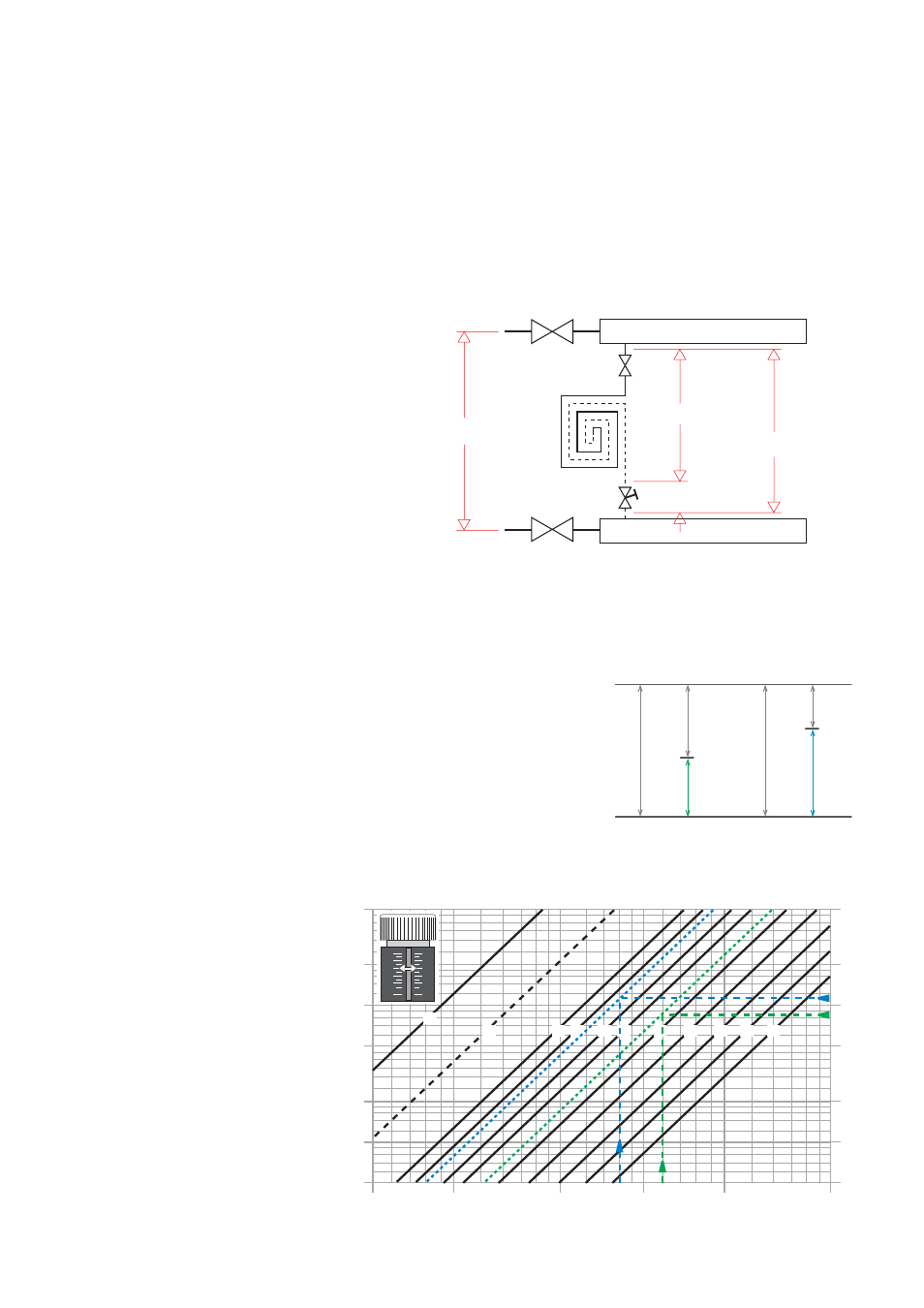
Use of the micrometric balancing valve
The micrometric balancing valves balance each individual circuit in the panels so that the actual design flow is obtained in each one.
Each individual circuit consists of a micrometric balancing valve, panel piping and shut-off valve. The following information must be taken into
account in order to calibrate the system correctly:
· The flow of fluid that must pass through each circuit (design data).
· The pressure loss that occurs in each circuit in accordance with the flow:
ΔP
Circuit
= ΔP
Loop
+ ΔP
SV
(1.3)
· The available head on the panel circuit or predetermined head:
H
Predetermined
≥ ΔP
Circuit
= ΔP
MV
+ ΔP
Loop
+ ΔP
SV
(1.4)
+ disadvantaged
In accordance with the passage of the flow G
Loop
the
micrometric valve must ensure an additional pressure loss
in all the circuits equal to the difference, indicated as ΔP
MV
(Δp micrometric valve).
To allow for an eventual increase in flow, the micrometric
valve of the circuit with the greatest pressure loss may
sometimes be considered as 80% open.
Once the two pieces of information, ΔP
MV
and G
Loop
,
are known for each circuit, the optimal adjustment curve
corresponding to the adjustment position of the valve must
be chosen from the graph.
H
Predetermined
≥ ΔP
Circuit
+ disadvantaged
ΔP
MV
ΔP
Circuit
ΔP
Tot
SV
MV