Specification summaries, Kv = 1 kv – Infloor Brass Manifold User Manual
Page 9
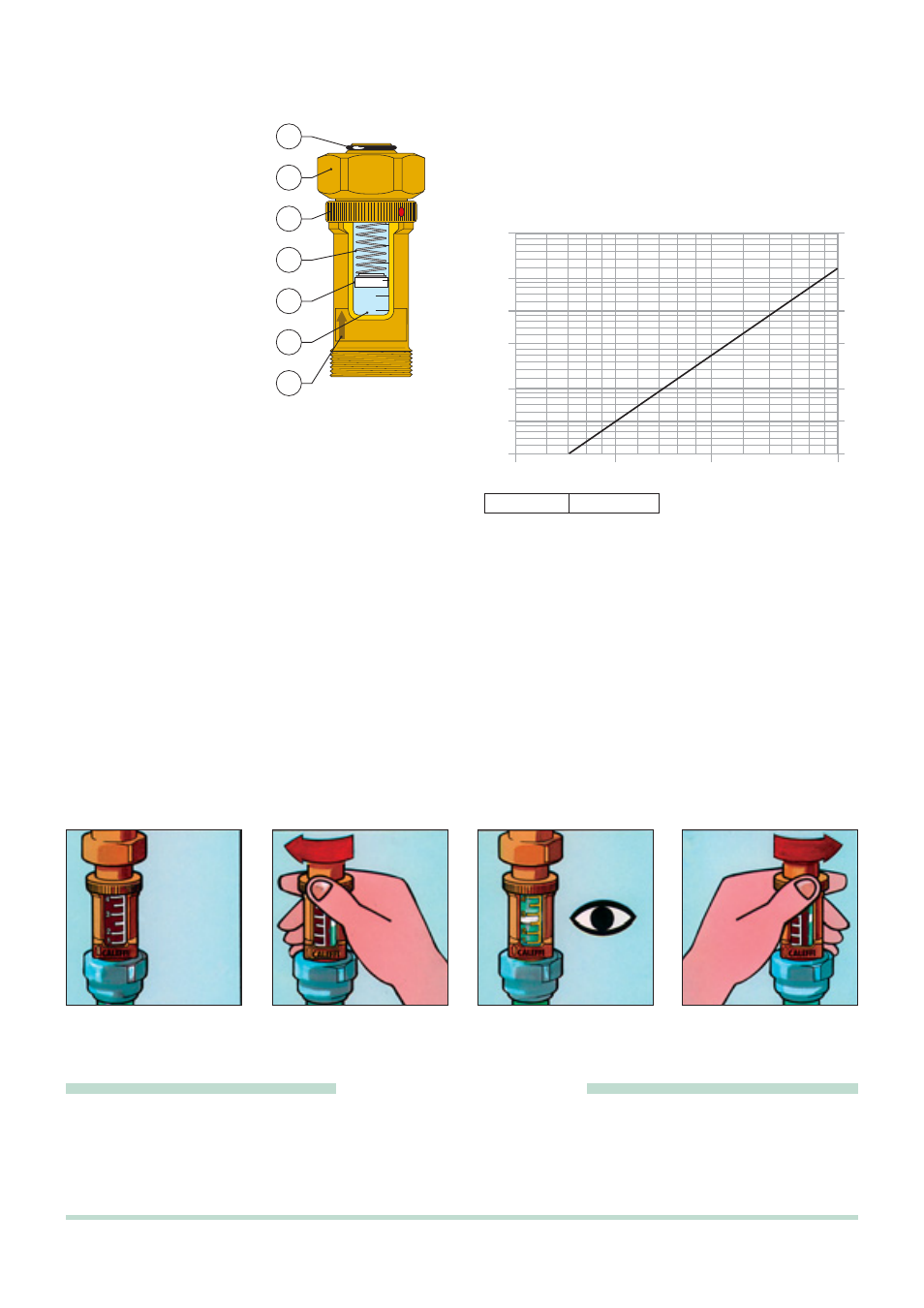
Operating principle
A spring (1) connected to a float
(2) is located inside the flow meter.
The force applied by the water to
the float as it flows through the
flow meter is countered in
proportion to the force applied by
the spring. When the flow
becomes stabilised at a particular
value, the float reaches a specific
position of equilibrium which also
serves as an indicator. The
system is balanced by moving the
calibration valve on the flow
manifold until it corresponds to the
design flow, which can be read on
the graduated scale printed on the
transparent cylinder (3).
The flow (
gpm) readout value
corresponds to the lower edge of
the float.
Installation
The flow meter must always be installed in a vertical position with
the flow indication arrow pointing up (7) to ensure the greatest
accuracy when measuring the flow.
Hydraulic characteristics
L/MIN
2
1
4
3
5
4
6
1
2
3
7
1000
100
G (l/h)
ΔP (mm w.g.)
2000
500
5000
50
60
70
80
90
120
140
160
180
200
600
700
800
900
1200
1400
1600
1800
2500
3000
3500
4000
4500
250
300
350
400
450
500
100
200
120
140
160
180
250
300
350
400
450
50
60
70
80
90
10
20
5
50
6
7
8
9
12
14
16
18
25
30
35
40
45
ΔP (kPa)
1
2
1,2
1,4
1,6
1,8
2,5
3,0
3,5
4,0
4,5
0,5
0,6
0,7
0,8
0,9
Construction details
Easy installation
The flow meter is equipped with a captive nut (4) that is mounted onto the manifold and sealed with an O-ring (5) mounted on the tail piece.
The captive nut solution simplifies assembly because it allows the flow meter to be mounted at the front of the manifold without having to change
the optimal readout position.
Dual readout scale
The flow meter is equipped with a spare graduated scale that can be used if flow needs to be checked or the system rebalanced but the float
can no longer be seen due to deposits on the transparent cylinder.
Turning the knurled nut (6) to the left will bring into view another scale in yellow that always stays clean due to the hermetic seal that prevents
water from entering while the system is operating.
The nut must be returned into the original position on the white scale after reading the measurement.
Flow meter with float. 3/4”M x 3/4”F nut threaded connections. Brass body, stainless steel measuring spring, EPDM seals,
transparent cylinder and internal protection in PSU, float-indicator in POM/PTFE. Medium: water and glycol solutions.
Maximum percentage of glycol 30%. Maximum working pressure: 6 bar. Temperature range
41–176 °F. Flow measurement scale:
1
/4–1 gal/min. Accuracy ± 10%. Dual readout scale.
SPECIFICATION SUMMARIES
Kv = 1 Kv
0,01
= 100
- Kv = flow in m
3
/h for a pressure loss of 1 bar
- Kv
0,01
= flow in l/h for a pressure loss of 1 kPa