3 kpa δp, 15 kpa δp, 0,5 kpa δp – Infloor Brass Manifold User Manual
Page 5: 0,03 kpa, 0,01 kpa δp, 0,007 kpa using the formula, We can add all the calculated terms to obtain: δp
20
1000
100
100
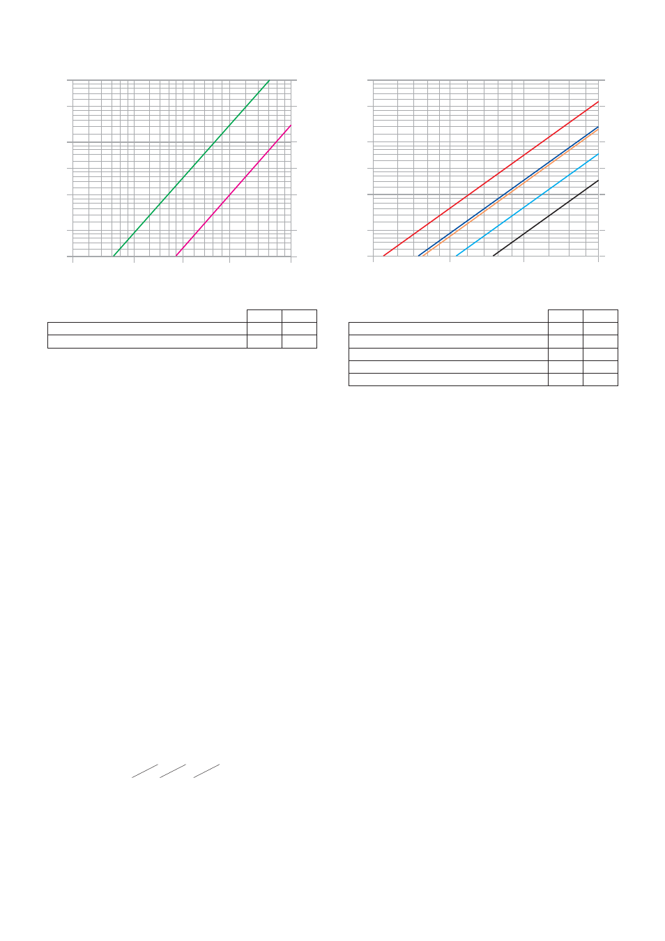
G (l/h)
ΔP (mm w.g.)
200
50
500
25
30
35
40
45
50
60
70
80
90
120
140
160
180
200
900
800
700
600
60
70
80
90
120
140
160
180
250
300
350
400
450
10
1
2
0,5
5
9
8
7
6
0,6
0,7
0,8
0,9
1,2
1,4
1,6
1,8
2,5
3
3,5
4
4,5
ΔP (kPa)
Micrometric balancing valve fully open
Shut-off valve
Kv
1,15
2,87
Kv
0,01
115
287
250
300
350
400
450
500
10
20
12
14
16
18
25
30
35
40
45
0,1
0,2
0,12
0,14
0,16
0,18
0,25
0,3
0,35
0,4
0,45
Flow manifold 3–7 outlets
Flow manifold 8–13 outlets
Return manifold 3–7 outlets
Return manifold 8–13 outlets
Ball valve
Kv
24*
17*
33,5*
23,5*
47,5
Kv
0,01
2400*
1700*
3350*
2350*
4750
1000
100
G (l/h)
ΔP (mm w.g.)
200
50
500
900
800
700
600
60
70
80
90
120
140
160
180
250
300
350
400
450
ΔP (kPa)
500
10
20
12
14
16
18
25
30
35
40
45
10
1
2
0,5
5
9
8
7
6
0,6
0,7
0,8
0,9
1,2
1,4
1,6
1,8
2,5
3
3,5
4
4,5
0,1
0,2
0,12
0,14
0,16
0,18
0,25
0,3
0,35
0,4
0,45
1000
600
700
800
900
1200
1400
1600
1800
2000
2500
3000
3500
4000
* Average value
Example of how to calculate the total pressure loss
Suppose we need to calculate the pressure loss of a manifold with three circuits with the following characteristics:
Total manifold flow: 400 l/h
The flow and pressure loss characteristics of the three piping loops are as follows:
Circuit 1
Circuit 2
Circuit 3
ΔP1= 10 kPa
ΔP2= 15 kPa
ΔP3= 7 kPa
(1.2)
G1= 120 l/h
G2= 200 l/h
G3= 80 l/h
Each segment of the formula
(1.1)
, is calculated using the following relationship:
ΔP=G
2
/Kv
0,01
2
· G= flow in l/h
· ΔP = pressure loss in kPa (1 kPa =100 mm w.g.)
· Kv
0,01
= flow in l/h through the device in question, with a pressure loss of 1 kPa
Note that the ΔP
Tot
must be calculated taking into account the circuit with the greatest pressure losses distributed along the entire piping loop of
the panel.
The circuit in question in our example is circuit 2.
Thus:
ΔP
MV
= 200
2
/115
2
= 3 kPa
ΔP
Loop
= 15 kPa
ΔP
SV
= 200
2
/287
2
= 0,5 kPa
ΔP
FM
= 400
2
/2400
2
= 0,03 kPa
}
Values obtained disregarding variations due to flow rate delivered to each branch circuit
ΔP
RM
= 400
2
/3350
2
= 0,01 kPa
ΔP
BV
= 400
2
/4750
2
= 0,007 kPa
Using the formula
(1.1)
we can add all the calculated terms to obtain:
ΔP
Tot
= 3 +15 + 0,5 + 0,03 + 0,01 + 0,0071 ≈ 18,5 kPa
Note:
We can ignore the three terms for the pressure losses associated with the ball valves and manifolds because their values are so low. Generally
speaking, the total pressure loss is fairly close to the pressure loss of the branched circuit of the panel.
- Kv = flow in m
3
/h for a pressure loss of 1 bar
- Kv
0,01
= flow in l/h for a pressure loss of 1 kPa