K-Patents PR-01-S User Manual
Page 10
INSTRUCTION MANUAL FOR K-PATENTS PR-01-S (-AX/FM/CS)
DOCUMENT/REVISION No. INM 1/14
Effective: May 15, 2009
8
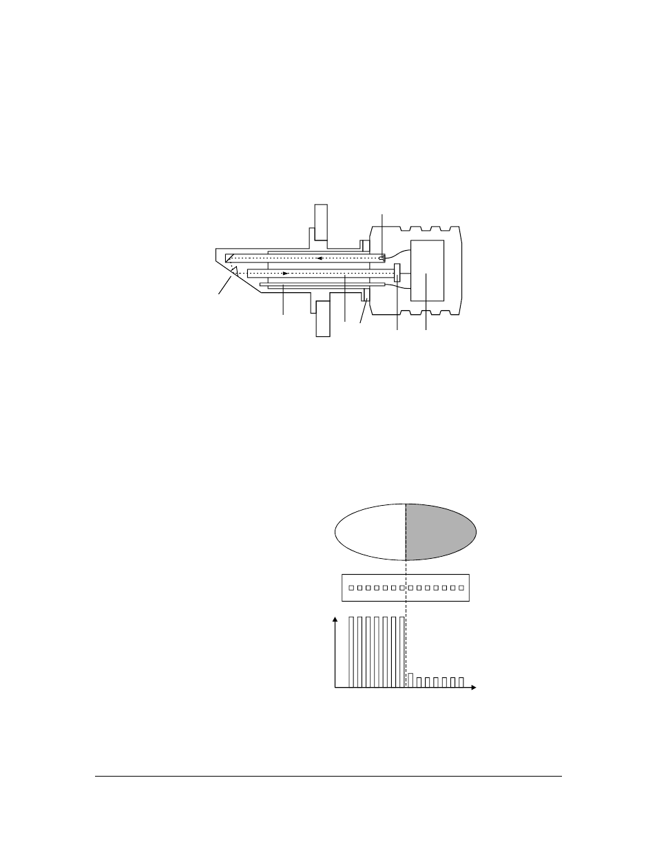
2.4. SENSOR DESCRIPTION
In the K-Patents Process Refractometer Sensor (Figure 2.40) the measurement prism (A) is flush mounted
in the oblique surface near the tip. The light source (B) is a light emitting diode.
K-Patents Process Refractometer uses a digital image detector (C). The image detector consists of 256
photocells in a row integrated on one chip.
A
B
C
D
E
F
G
Figure 2.40
Sensor structure.
The image detector output is a pulse train as shown in Figure 2.41. This number of high pulses corresponds
to the position of the shadow edge in the optical image. The number of high pulses is a direct measure of
the critical angle. The image digitizer (E) transforms this pulse train to a serial digital signal. This serial
signal transmits a package containing a complete description of the optical image and temperature data to
the Indicating transmitter.
For automatic temperature compensation, the sensor tip contains a process temperature probe (F).
The digital image sensor (C) is separated from the process heat by fiber optics (D) and the thermal isolation
(G). It is housed in the air-cooled sensor head.
a. Optical image
b. Detector window and the photocells
c. Pulse train from the detector.
a
b
c
TIME
V
Figure 2.41
Image detector system.