Klamp table, Assembly – Kreg KKS1000 Klamp Table User Manual
Page 2
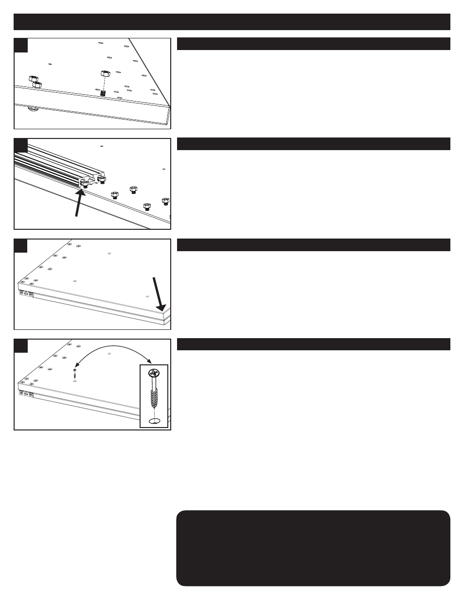
1
2
STEP ONE
Begin by positioning the Table Base at the corner of your workbench so that the
pre-drilled holes hang over the surface with the countersunk side facing down.
Insert the 1/4-20 x 1-7/16 Truss Head Bolts up through the countersunk
holes on the bottom side of the Table Base and thread on the corresponding
nuts until the bolts are flush with the top of each nut, as shown in image 1.
There are 38 holes in total.
3
Klamp Table
TM
Assembly
4
Ensuring that the two lengths of Klamp Trak™ are perfectly perpendicular
(90 degree angle) to each other will give you the best possible results when
using the included Klamp Blocks™ to align face-frames and other project
stock. For a more accurate 90 degree angle, you may use a combination
square (instead of the Table Top) to align the Trak.
NOTE
STEP TWO
With all the bolts inserted and nuts threaded on, begin guiding both pieces of
Klamp Trak™ over the bolts; raising, lowering, and rotating them as
necessary, as shown in image 2. Once the trak has been positioned, do
NOT tighten the bolts down. You will need to make adjustments to the Trak’s
position after the next step.
STEP THREE
With both lengths of Trak in place (but not yet tightened down), place the 3/4”
Table Top face-down on your work surface so that the pre-drilled holes are
visible. Then, while securing each length of Trak with your hands, carefully flip
the Table Base and Klamp Trak™ assembly and place it face-down over the
Table Top so that the Top rests in the space between the Trak lengths. Next,
slide the Table Base assembly slightly so that the corner of the Top and Base
opposite the Klamp Table™ sticker is perfectly flush, as shown in image 3.
STEP FOUR
With the two tables lined up, you should now be able to install the flat-head
screws and join the them together. Place the eight 1-5/8” flat-head screws
in the pre-drilled holes of the Table Base and make sure that screw tips fall
gently into the pre-drilled holes of the Table Top. I
f all eight screws fall
into the holes on the Top you are assured the table surfaces will be lined up
properly. You may begin to drive the screws as shown in image 4, using
a #2 Phillips Driver. For an optimum hold, and to reduce the possibility of
damage to the table’s surface, do not overdrive the screws.
After the Table Top and Table Base are secured to each other, push the
Klamp Trak™ towards the center of the assembly until it lays snug against
the Table Top and flush to the outside edges. Once the Trak is positioned,
use a #3 Phillips driver to tighten the bolts down completely, securing the Trak
into place. Repeat this step for the second length of Trak.