Benchtop router table assembly instructions – Kreg PRS2100 Precision Benchtop Router Table User Manual
Page 6
Benchtop Router Table Assembly Instructions
5.
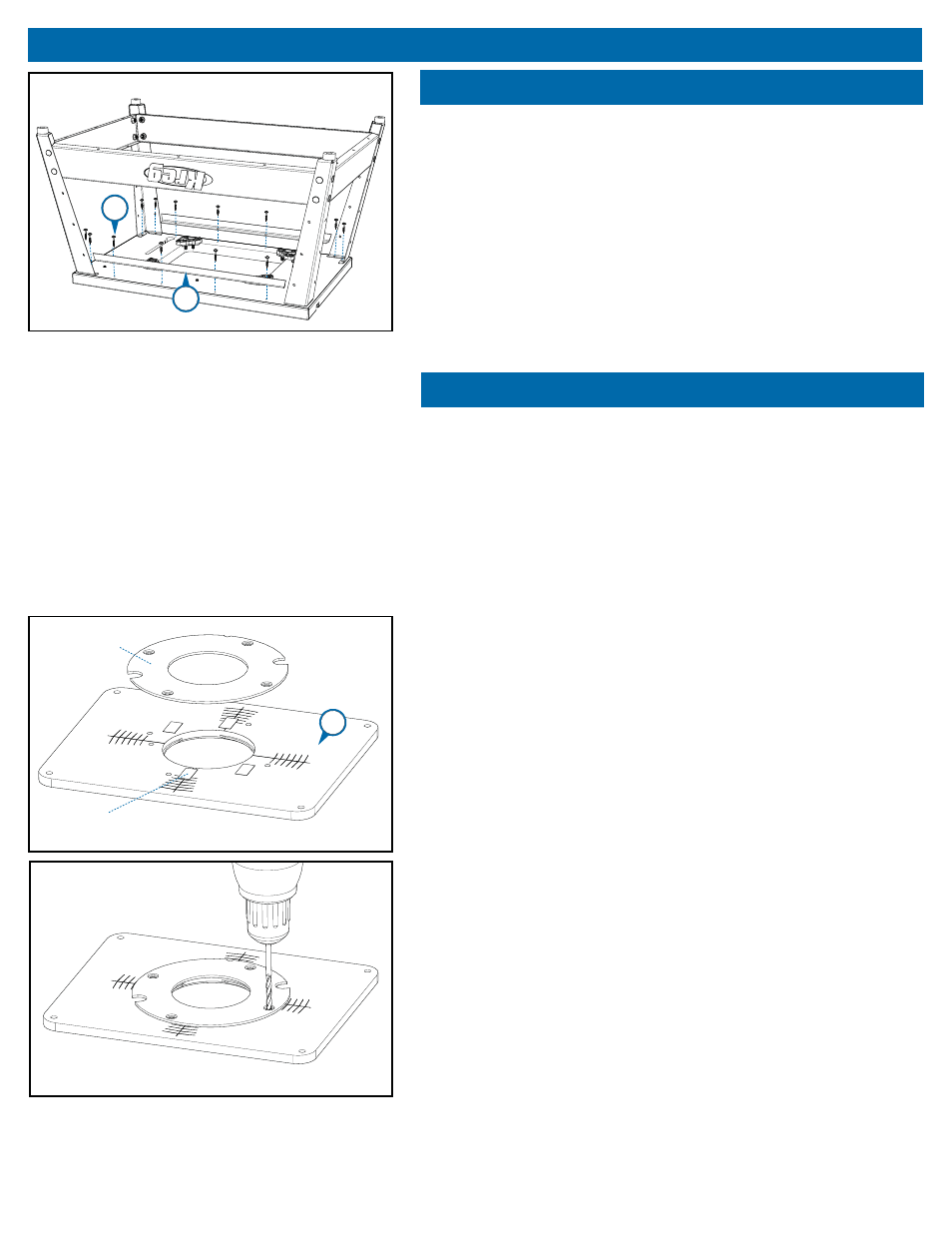
Step 4
Position the legs/rails assembly on the bottom face of the router table top
with the Kreg logo facing the front. (The miter-gauge track is at the front
edge of the table top.) Align the holes in the top fl anges of the legs with
the pilot holes in the table top. Fasten the legs to the top with eight ¾"
coarse-thread screws (#17). Be careful not to strip out the pilot holes by
over-tightening the screws.
Tighten all sixteen nuts on the leg/rail assembly.
Position the braces (#7) on the bottom face of the table top (#10) along
the long edges. Align the holes in the braces with the pilot holes in the
table top. Fasten the braces to the top with eight ¾" coarse-thread
screws (#17).
Step 5
There is not a standard hole pattern for the machine screws that
fasten the sub-base to a router base. You’ll drill your own holes in
this insert plate to fi t your router. When aligning the router sub-base
with the target pattern on the insert plate, adjust the orientation
so you’ll have easy access to the router controls when the router
and plate are installed in your router table. The router handles do
not need to be square with the table or plate for proper operation.
Easy access to the on/off switch, depth-adjustment lock, and other
controls should be your priority when attaching the router to the
insert plate.
Place the insert plate (#18) on your workbench with the target pattern
facing up. Remove the sub-base from your router and select a drill bit
that fi ts the mounting holes. If your router is equipped with a built-in
lift system, select a bit that fi ts the lift-access hole. Apply several small
pieces of double-faced tape to the insert plate. Now, center the sub-base
on the plate, using the concentric arcs of the target pattern as guides.
Keep in mind where you want the router controls positioned. Make sure
that none of the holes you are about to drill align with the threaded hole
for the start pin. Press the sub-base fi rmly onto the insert plate.
Using the holes in the sub-base as guides, drill the holes in the insert
plate with a drill press or hand drill. Performing this operation on a drill
press ensures that the holes are perpendicular to the plate. Before
drilling, securely clamp the insert plate to your drill-press table or bench
to prevent it from moving as you drill. Whether you use a drill press or
hand drill, place a scrap piece of wood under the insert plate to reduce
chipping as the drill bit passes through the plate.
With the holes drilled, remove the sub-base from the insert plate. Flip
the plate over and countersink the mounting holes so the machine screw
heads sit slightly below the plate surface when tightened down. Store the
router sub-base in a convenient place. You will need it when you remove
your router from the router table for handheld routing.
sub-base
Double-faced tape
17
7
18