Benchtop router table assembly instructions – Kreg PRS2100 Precision Benchtop Router Table User Manual
Page 8
Benchtop Router Table Assembly Instructions
7.
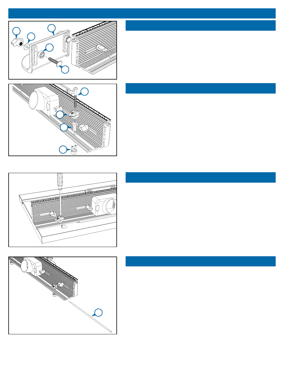
Step 10
Assemble the bit guard (#30) using two ¼-20 x 1¼" T-bolts (#31), two
spacers (#32), two ¼" brass fl at washers (#28), and two T-knobs (#29),
as shown. Slide the T-bolt heads into the T-slot at the top front edge of
the fence extrusion and tighten the knobs.
Step 11
Assemble the ¼-turn fence locks using the fence-lock bases (#33), fence-
lock handles (#34), ¼-20 x 2½” Phillips panhead machine screws (#35) and
fence-lock anchors (#36). Slip the machine screws through the handles and
bases and drop the handle/base/machine screw assemblies through the
holes in the base fl ange of the fence extrusion. Thread the machine screws
into the fence-lock anchors until just the tips of the anchor “fi ngers” engage
the notches in the bases. [Because the anchor fi ngers engage the base
notches, the anchors can’t turn and bind in the table-top slots or change the
fence-lock tension.]
Note: When using the fence with a table top thinner than 1 ⅛”, carefully trim the
ends of the anchor fi ngers so they don’t bottom out in the cam-post notches.
Step 12
Mount the assembled fence on the router-table top by dropping the fence-
lock anchors (#36) through the key holes in the table top. D-shaped holes
in the fence automatically orient the fence-lock bases. Position the fence-
lock handles pointing away from the fence and angled 45 degrees to the
right [viewed from the back of the fence]. This is the unlocked position for
the handles. Slide the fence forward, engaging the fence-lock anchors in
the table-top fence slots. To adjust fence-lock tension, rotate the handles
¼-turn clockwise [locked position]. Tighten the machine screws (#35) with
a screw driver until the clamps are tight enough to hold the fence in place.
Now when you rotate the handles ¼-turn counterclockwise to release the
fence, it should move freely.
Step 13
To store the jointing rods (#37), slide them into the round channel at the
back edge of the base fl ange of the fence extrusion. For instructions on
how to use these rods for jointing on your router table, see JOINTING
under the section USING YOUR ROUTER TABLE.
31
32
30
28
29
35
36
34
33
37