Benchtop router table assembly instructions – Kreg PRS2100 Precision Benchtop Router Table User Manual
Page 7
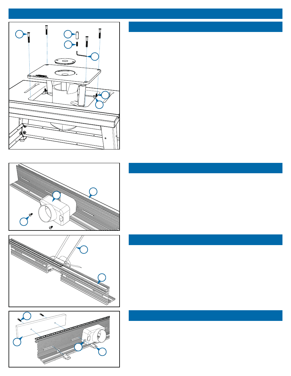
Benchtop Router Table Assembly Instructions
6.
Step 6
Attach the router base to the insert plate, using the screws that attached
the sub-base to the router base. Depending on the thickness of your router
sub-base, it may be necessary to purchase longer screws. Make certain
that the screws are long enough to fully thread into the router base. If you
are mounting a fi xed-base router, install the motor unit in the router base.
Place the insert plate with the router attached in the table top opening,
resting it on the eight set screws (#16) in the plate levelers (#13). Using
the hex wrench (#15), adjust the set screws from under the table to align
the surfaces of the plate and the table. Check the alignment with a steel
ruler or the edge of a jointed board. Make sure all eight set screws are in
equal contact with the insert plate. Thread the four ¼-20 x 1¾" machine
screws (#19) through the countersunk holes in the insert plate and into the
center hole on each leveler and snug them down. The machine screws and
set screws apply pressure in opposing directions, locking the insert plate
in place. Some loosening or tightening of the lock down screws and set
screws may be necessary to fi ne-tune the alignment.
Thread the ¼-20 x ¾" set screw (#20) into the bottom of the brass starting
pin (#21) and tighten the assembly with a fl at-blade screw driver and ⅛"
hex wrench (#15). When ready for use, thread the starting pin assembly
into the threaded hole in the insert plate and tighten it.
Step 7
Mount the vacuum port (#23) to the fence extrusion (#22) using two
#10-32 x ⅜" Phillips pan head machine screws (#24).
Step 8
Using a tape measure and pencil, locate and mark the center point of
the top edge of the fence extrusion (#22). Position the zero mark of the
self-adhesive center-reading tape (#25) at the pencil mark and remove
the protective backing as you adhere the tape to the extrusion. With the
tape adhered, trim the excess fl ush with each end of the extrusion with
metal snips.
Step 9
Install the two fence faces (#26) using two ¼-20 x 1½" fl at head machine
screws (#27) inserted through the front of each fence face. Secure the
machine screws at the back with two ¼" brass fl at washers (#28) and
two T-knobs (#29) for each fence face.
19
21
20
15
16
13
22
23
24
22
25
26
28
29
27