1 status – LSC Lighting GenVI User Manual
Page 10
Menu System
GenVI Dimmer
Operator Manual V1.0
Page 6
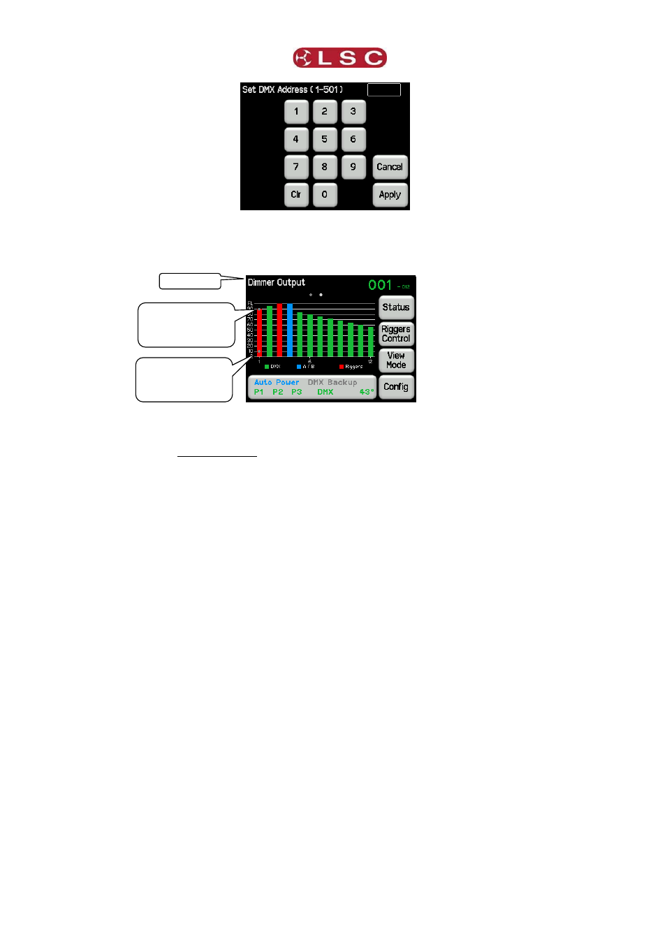
Enter the DMX address for the first channel in this GenVI then press Apply.
3.3.2
Dimmer Output Home Page
“Dimmer Output” Home Page
The “Dimmer Output” home page has a large display of output levels of the dimmer channels
that also shows the control source of each channel according to the colour code.
Green = DMX
Blue = Auto Power or Backup (DMX loss) memory
Red = Rigger control (via the touch screen)
Channels are controlled on a HTP (highest Takes Precedence) basis. If multiple sources are
controlling a channel (such as DMX and Riggers control) then the highest level will be output
and will hence determine the colour of the bargarph.
If a minimum or maximum level has been set for a channel they are indicated by grey dots
on the channels bargraph.
The top right corner of the screen shows the DMX address information.
If a 1 to 1 patch is implemented it shows the DMX addresses of the first and last
channels of the dimmer rack.
If channels are individually patched it shows the word “Patched”.
The “Dimmer Output” home page also and provides access to the Status menu.
3.3.2.1
Status
On the “Dimmer Output” home page, pressing Status shows the following information….
Grey dot shows
“Minimum” level
set for a channel.
Grey dot shows
“Maximum” level
set for a channel.
Page name