Chapter 3: communications – Microcom 412 User Manual
Page 21
412 Operators Manual
13
CHAPTER 3: COMMUNICATIONS
The 412 can be interfaced to PC's, mini-computers, main frames, and special purpose
machines. It is capable of serial RS-232, RS-485 or Centronics® parallel communication. The
following sections explain the communication interfaces.
Out of the box, unless otherwise requested, the serial port communicates at 9600 bits per
second, 8 data bits, 1 stop bit and no parity with both hardware and software handshaking.
This configuration may be changed as shown in Appendix E.
3.1
CABLE PINOUT
Table 2a shows the signals of the 9 pin RS-232 serial port and Table 2b shows the signals of
the 2 and 4 wire RS-485 . If serial communication is selected and XON/XOFF hand shaking is
used, the only signals the 412 requires are the RXD, TXD, and GND signals. If hardware
(RTS/CTS) hand shaking is used, a RTS signal is provided. XON/XOFF may be disabled
through software dip switch #1 (see Chapter 5). The other signals are offered in the event the
host computer requires them.
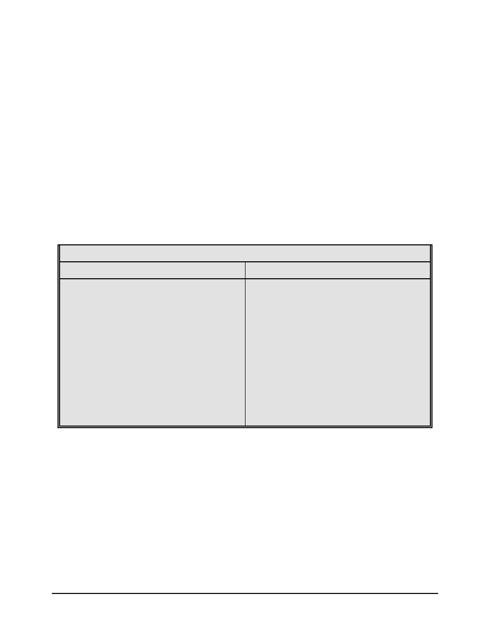
RS-232 Serial Port Configuration
25 TO 9 PIN
9 TO 9 PIN
State 412 Direction PC
HI 1 DCD---->---- DCD 8
XX 2 TXD---->---- RXD 3
XX 3 RXD----<---- TXD 2
HI 4 DSR----<---- DTR 20
LO 5 GND---<->--- GND 7
HI 6 DTR---->---- DSR 6
DC 7 CTS----<---- RTS 4
XX 8 RTS---->---- CTS 5
HI 9 +5V
DE-9 DB-25
DC = Do Not Care
XX = Indeterminate
State 412 Direction PC
XX 1 DCD---->---- DCD 1
XX 2 TXD---->---- RXD 2
XX 3 RXD----<---- TXD 3
HI 4 DSR----<---- DTR 4
LO 5 GND---<->--- GND 5
HI 6 DTR---->---- DSR 6
DC 7 CTS----<---- RTS 7
XX 8 RTS---->---- CTS 8
HI 9 +5V---->---- +5V 9
DE-9 DE-9
DC = Do Not Care
XX = Indeterminate
Table 2a
Table 2b describes the RS-485 two and four wire pinouts. The internal jumper block (JP6) is
used to select the mode. To enable two wire communication, a jumper shunt should be place
over pins 2 and 3. The four wire mode is selected by placing the shunt over pins 1 and 2.
Table 2b also contains entries called SW1, SW2, SW3 and SW4. These pins are provide to
allow automatic address selection via the external cable wiring. To use this method of address
assignment, the printers internal jumpers (JP7, JP9, JP10 and JP11) must each have a shunt
installed between pins 2 and 3. (Placing the shunt on pins 1 and 2 will disable this feature and
require the use of the rear panel switches.)