Microcom 412 User Manual
Page 22
Communications
Chapter 3
412 Operators Manual
14
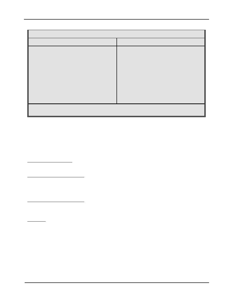
RS-485 Serial Port Configuration
Two Wire Interface
Four Wire Interface
1 Not Used or SW3 *
2 Not Used
3 Transmit- / Receive-
4 Not Used or SW2 *
5 GND
6 Not Used
7 Not Used or SW1 *
8 Transmit+ / Receive+
9 +5 or SW4 *
DE-9
1 Not Used or SW3 *
2 Transmit-
3 Receive-
4 Not Used or SW2 *
5 GND
6 Transmit+
7 Not Used or SW1 *
8 Receive+
9 +5V or SW4 *
DE-9
* The function of this pin is determined by JP7, JP9, JP10 and JP11.
Table 2b
3.2
PRINTER CABLES
The 412 uses standard cables which may be purchased through Microcom Corporation or a
local computer supply company. NULL modem adapters are not normally used because the
printer is DCE equipment
For parallel connections, use a standard 25 pin to 36 pin Centronics® printer cable, connected
from the desired parallel port of the host computer to the 36 pin connector on the model 412.
For RS-232 serial connections,
25 pin serial port - Use a 25 pin female to 9 pin male serial cable.
9 pin serial port - Use a 9 pin female to 9 pin male cable.
For RS-485 serial connections,
The RS-232 cables mentioned above can be used to connect a single printer via RS-485.
Custom cables or adapters may be required in order to connect multiple printers.
Warning: Connecting a serial port to a parallel port may damage the printer and/or computer.
3.3
MULTIDROP COMMUNICATIONS
Multidrop mode allows a single host to communicate with up to 31 printers in a network. With a
separate address for each printer, the host can force some printers into a sleep mode while
the rest continue to respond to the host. Multidrop mode will function using RS-232 or RS-485.
Special care should be taken when using RS-232 due to the loads placed on the RS-232 port
of the host. The twelve position dip switch, located on the rear of the printer, is used to control
the operation of this feature.