Bluetooth interface – NavCom LAND-PAK Quick Start Rev.B User Manual
Page 6
6 of 7
LAND-PAK Quick-Start Guide, Rev. C
Figure 4: Pole Clamp and Cradle
Refer to Figure 4 for the steps below:
62. Connect the rover pole clamp to the Nautiz cradle, if
necessary:
a. Insert the cradle quick-release adapter into the hole
in the pole clamp.
b. Depress the button on the pole clamp and, if
necessary, twist the cradle to the desired position by
inserting the small peg into one of the available
holes on pole clamp.
c. Release the black button on the pole clamp to lock
the assembly in place.
Figure 5: Mounting the MicroSurvey Nautiz X7
Refer to Figure 5 for the steps below:
63. Connect the clamp assembly to the rover pole:
a. Loosen the knob on the pole clamp.
b. Connect the pole clamp to the rover pole above the
level so that it does not obscure the level from view.
c. Tighten the knob.
64. Mount the Nautiz X7 on the cradle clamp and tighten
the cradle knob.
Do not over-tighten the cradle. Over tightening
may cause damage to the Nautiz X7 screen
Do not lean the pole in a location where the
equipment is likely to fall. Though the electronic
products are tested for a pole drop, repeated
drops or drops on the wrong axis may cause
equipment damage.
65. Insert the two lithium-ion battery packs into the SF-3040
GNSS receiver. Refer to Chapter 3 (Battery Charging)
of the SF-3040 GNSS Product User Guide, if
necessary.
66. Extend the rover pole to the maximum height and snap
it into place. This may require turning the top pole to
align the spring-loaded clasps with the bottom pole.
67. Tighten the connector at the base of the extension to
secure the extension pole.
68. Extending the rover pole reduces the possibility of
satellite signal blockage by passing pedestrians or
vehicles.
69. Screw the receiver antenna onto the SF-3040.
70. Mount the SF-3040 to the top of the rover pole and
screw into place.
Bluetooth Interface
71. Log on to FieldGenius and select a project or create a
new one (see the Field Genius User Guide for detailed
instructions).
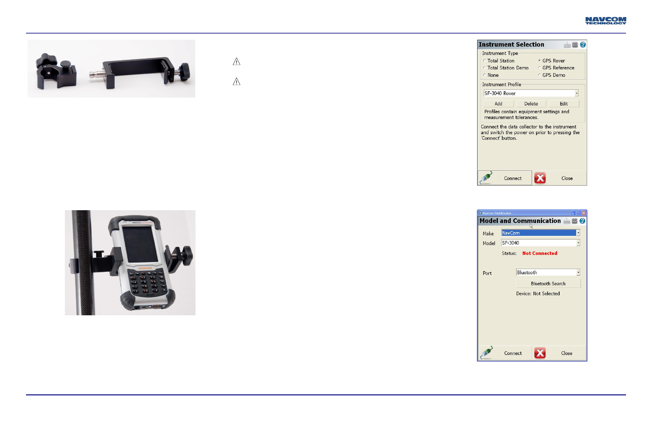
72. On the Instrument Selection dialog box (refer to
Figure 6), select GPS Rover.
a. Separate profiles are maintained in the FieldGenius
database so that one data collector can connect to
multiple devices. Select and name the unit being
configured.
Figure 6: Instrument Selection
73. Click Edit to set the data collector interface up.
Figure 7: Model and Communication