4 connections, 1 power connection 4.1.1 pin-out dc1 and dc2 (db9), 2 gpi power supply status outputs – Nevion FR-2RU-10-2 User Manual
Page 8: 4connections, 1 power connection
FR-2RU-10-2
Rev. N
nevion.com | 8
4
Connections
4.1 Power connection
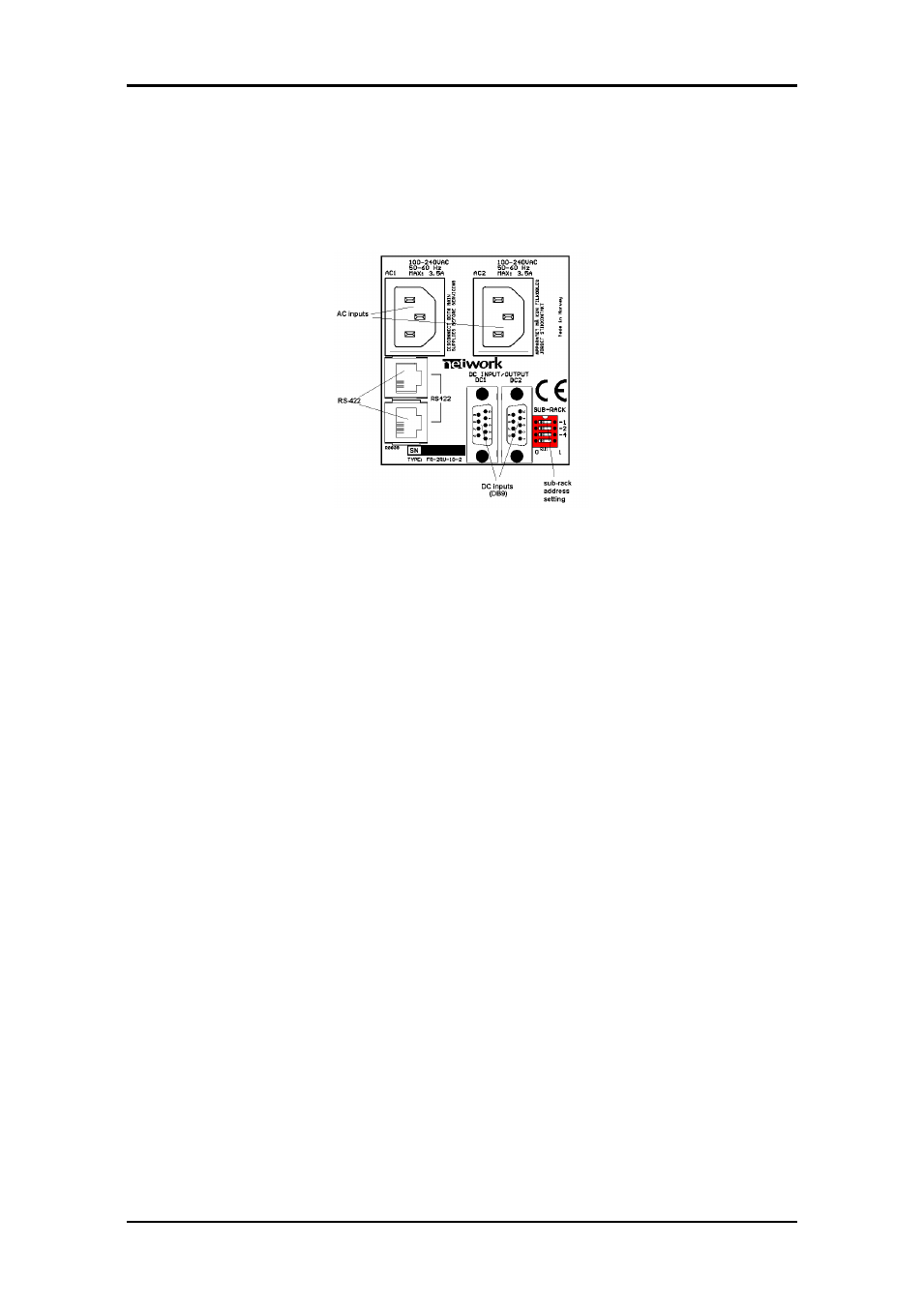
Figure 3 shows the power connections of the sub-rack as well as the RS-422
connections and the DIP-switches for address setting of the sub-rack.
Figure 3: Connector module for the power supply.
AC: Connect mains to the sub-rack with a mains cord with an IEC 320 connector.
DC: Connect the DB9 male connector from the external DC power supply to the main
unit. Tighten the screws to ensure a proper contact. The DC inputs have the same
function; the left input (DC1) is for the left power module when seen from the rear and
DC2 is for the right power module when seen from the rear.
4.1.1 Pin-out DC1 and DC2 (DB9)
The maximum current drawn from each pin of the DB9 connector is 2,5A.
Pin #1
GND for DC
Pin #2
+5V
Output, Max. current: 6A
Pin #3
Relay
GPI Output, Normally Open
Pin #4
+15V
Output, Max. current: 1A
Pin #5
Positive part of 48VDC supply
Input
Pin #6
-5V
Output, Max. current: 1A
Pin #7
Relay
GPI Output, Normally Open
Pin #8
-15V
Output, Max. current: 1A
Pin #9
Negative part of 48VDC supply
Input
Pin 1, 2, 4, 6 and 8 are common to both DC1 and DC2. (I.e. they are physically
connected).
A green LED will light on the front when the power supply is in operation.
4.1.2 GPI Power Supply Status outputs
The GPI module status outputs can be used for wiring up alarms for third party control
systems.