3 connections, 4 sync input – Nevion FRS-HD-CHO User Manual
Page 12
FRS-HD-CHO
Rev. 9
nevion.com | 12
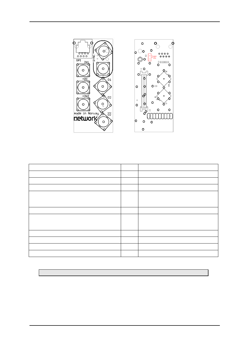
3.3 Connections
Figure 5: FRS-HD-CHO-C1 backplane
right: connection side
left: component side
The backplane for the FRS-HD-CHO is labeled FRS-HD-CHO-C1. The table below shows
the connectors and their functions.
Function
Label
Connector type
HD/SD-SDI or ASI input 1
IN1
BNC
HD/SD-SDI or ASI input 2
IN2
BNC
HD/SD-SDI or ASI output 1
O1
BNC
HD/SD-SDI output 1, inverted
(ASI is a
polarized signal, i.e. the inverted signal is not
valid ASI unless inverted a second time)
___
O1
BNC
HD/SD-SDI or ASI output 2
O2
BNC
HD/SD-SDI output 2, inverted
(ASI is a
polarized signal, i.e. the inverted signal is not
valid ASI unless inverted a second time)
___
O2
BNC
Black & Burst/ tri-level input
SYNC BNC
Black & Burst/ tri-level input
SYNC BNC
GPI in
GPI
TP45, pin 5 & 6
GPI out
GPI
TP45 pin 1, 2, 3, 4, 7 (pin 8 = GND)
Table 2: Connector functions
Unused SDI/ASI-inputs/outputs must be terminated with 75 Ohm.
3.4 Sync input
The two sync inputs on the backplane are internally connected. It is possible to use one as
input and the other as a looped output. The backplane also features a switchable
termination.
By setting the “red” switch in the upper right of Figure 5 to the „On‟ position the
sync input will be terminated to 75 Ohms.