Frs-hd-cho rev. 9, 4 dip switch functions – Nevion FRS-HD-CHO User Manual
Page 9
FRS-HD-CHO
Rev. 9
nevion.com | 9
The factory reset is initiated by setting DIPs 15 and 16 to
the „On‟ position and booting the
module. All inputs signals should be removed. The status LED will stay permanently orange,
and the module will not complete its start-up. DIP 15
should then be returned to the „Off‟
position, while DIP 16 should be set to the desired mode of operation before the module is
booted again. This starts the actual internal reset process, and the module should now be left
powered for at least 10 seconds or the complete set of default setting may not be stored
properly. If necessary, the reset operation can be performed multiple times.
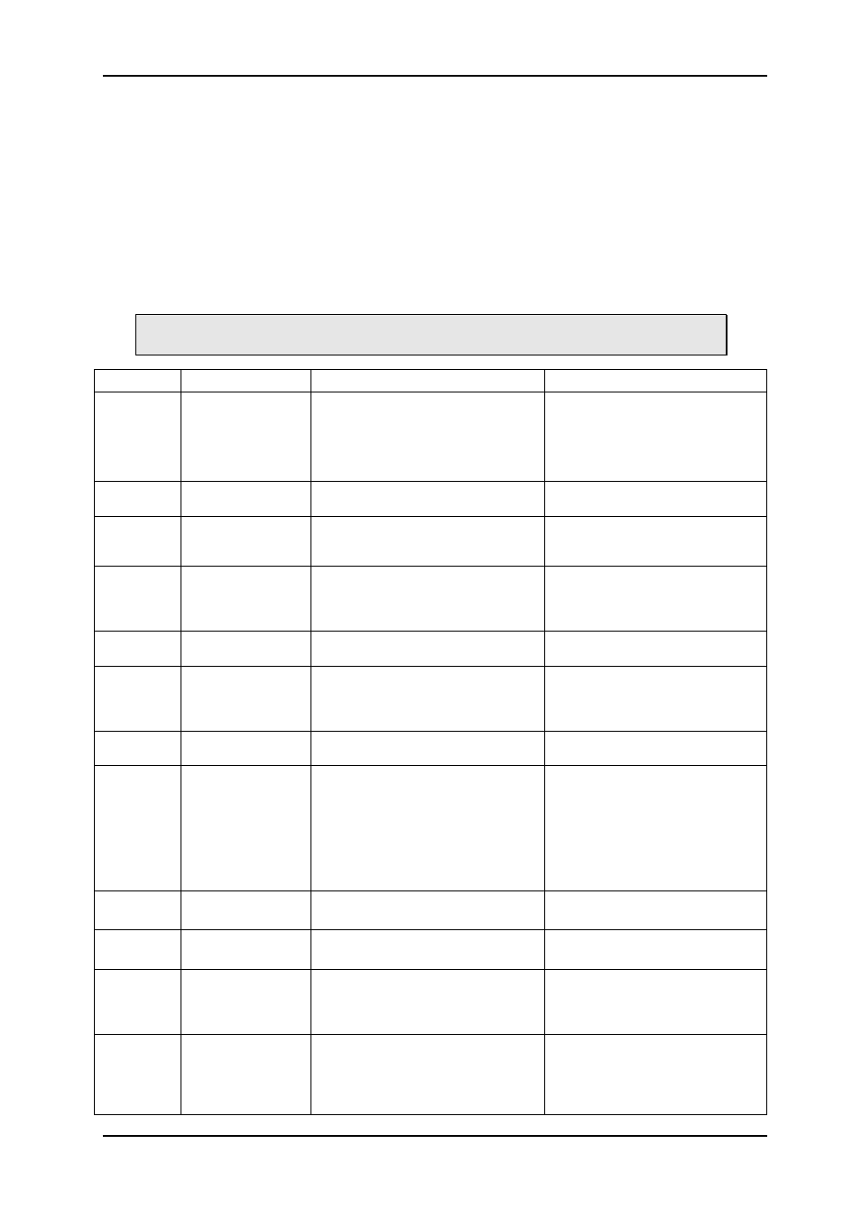
3.1.4 DIP switch functions
The two sets of DIP switches are labeled with a number running from 1 to 15. The 16
th
DIP is
labeled OVR.
Note that the left DIP switch of the horizontal DIP package is number 1. The top
DIP switch of the vertical DIP package is number 9.
Switch # Function name
Function DIPs
Comment
1
ASI/SDI input
mode
(FRS-HD-CHO-ASI
only)
Off: input is SDI
On: input is ASI
(For valid ASI output, DIP12 and/or
DIP13 must also be set to the
„Through position‟)
FRS-HD-CHO-ASI only.
Note: Firmware older than ver. 1.10
use this DIP for a latch on/off input
setting.
2
CHO priority
Off = In1
On = In2
3
---
Reserved
Note: Firmware older than ver. 1.10
use this DIP for selection between
Loss Of Signal and Loss Of Lock.
4-5
Lock & Hold time
DIP[5 6] = [Off Off] => Minimum
DIP[5 6] = [Off On] => 1s
DIP[5 6] = [On Off] => 4s
DIP[5 6] = [On On] => Reserved
Only valid if latch is on
6
Audio gen
Off = 1kHz Sine
On = Black sound
7
Emb. enable
Off: No audio embedded
On: Audio embedded
When off, the audio is left un-
touched on the SDI stream. When
on, the audio configured to be em-
bedded is embedded into the SDI.
8
GPIO setup
Off: SDI-CHO-2x1 mode
On: FRS-HD-SDI mode
See the GPI input output
description below.
9 - 11
Frame delay
DIP[9 10 11] = [Off Off Off] => 0 frms
DIP[9 10 11] = [Off Off On] => 1 frms
DIP[9 10 11] = [Off On Off] => 2 frms
DIP[9 10 11] = [Off On On] => 3 frms
DIP[9 10 11] = [On Off Off] => 4 frms
DIP[9 10 11] = [On Off On] => 5 frms
DIP[9 10 11] = [On On Off] => 6 frms
DIP[9 10 11] = [On On On] => 7 frms
With a sync-input present, this sets
the minimum frames delay.
Without a sync-input present this
sets the no. of frames delay relative
to the input.
12
SDI OUT 1
Off: through mode
On: processed mode
In through mode the video only
goes through a re-clocker.
13
SDI OUT 2
Off: through mode
On: processed mode
In through mode the video only
goes through a re-clocker.
14
Video Generator
Off: Color bar
On: Black field
This is the video generator signal
that is shown when video is
detected lost according to the
fallback rule set in GYDA.
15
RESET
Off: Use values preset by GYDA.
On: RESET to factory defaults
To reset, both DIP 15 and DIP16
must be set on before powering on.
DIP 15 and 16 is read at power up.
The reset is not done until DIP 15 is
set back to off and re-powered.