5 functional description, 2 sdi data path, 3 video input selection – Nevion FRS-HD-CHO User Manual
Page 15
FRS-HD-CHO
Rev. 9
nevion.com | 15
5 Functional description
5.1 Selection of input signal type (FRS-HD-CHO-ASI only)
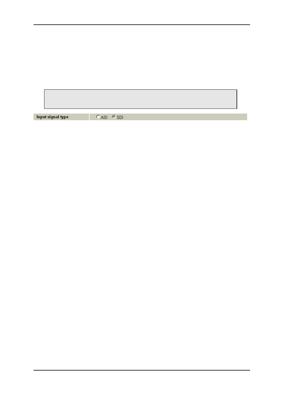
If the optional ASI upgrade has been purchased, the top of the configuration page will be a
selector between SDI input mode and ASI input mode. In ASI mode, the module will not lock
to a non-ASI SDI signal. The ASI signal will not pass through the FPGA, it will only be
passed to the FPGA, enabling the FPGA to look for valid ASI data.
In order to get an output in ASI mode, the video output must also be taken from
the Pass-through position (see 5.10, Video output selection), meaning that the
video output is re-clocked only.
Figure 6: Gyda view of the input signal type selector
5.2 SDI data path
HD/SD-SDI input is selected from input 1 or 2, equalized, re-clocked and transferred to a
processing unit. Here the signal is first sent through a de-glitcher that cleans up errors that
might appear on input signal, for instance due to switching. After the de-glitcher the parallel
video is split in two paths, one going directly to a frame-store buffer, the other sent to the
audio de-embedder.
The 16 audio channels coming from the de-embedder are bundled in pairs and sent to an
audio store buffer (being the same as the frame store buffer). The audio is fetched from the
audio store buffer according to a user specified delay and sent to an Audio Cross Point. The
output of the Audio Cross Point can be any pair of audio channels de-embedded from the
incoming video stream, an internal 1 kHz sine or an internal
“black sound”. “Black sound” is
in function mute, but it produces a waveform pattern which is different from mute. Each
channel pair from the cross point outputs enters an Audio Processing Block, where the
paired channels may be level adjusted and shuffled. After the audio processing block the
audio enters the Audio Embedder.
The video (with audio still inserted) is fetched from the frame buffer with the user specified
delay and sent to a Video processing block (gain, offset and hard clip legalizing), followed by
an EDH processing block. After the EDH block the video and audio is embedded according
to the user settings and the video is sent from the processing unit to a re-clocker. Here the
signal is converted back to SDI and sent to a 2x2 output switch.
The buffered output switch is a 2x2 cross point switching between an equalized and re-
clocked input (through) and a video processed input (processed). The two outputs are sent to
two paired (non-inverting and inverting) outputs.
5.3 Video input selection
The FRS-HD-CHO has two electrical inputs. The input can be chosen either by an automatic
selection with priorities and rule of switching, or by manual selection. If there is a sync input
connected, the board will switch the signals on the switching line of the present format.