4 operation, 1 front panel led indicators, 2 gpi alarms – Nevion FRS-HD-CHO User Manual
Page 13
FRS-HD-CHO
Rev. 9
nevion.com | 13
4 Operation
4.1 Front panel LED indicators
Diode \ state
Red LED
Orange LED
Green LED
No light
Card status
PTC fuse has
been triggered
or FPGA
programming
has failed
Module has not
been
programmed,
RESET and
OVR DIPS are
on or module is
updating
firmware.
Module is OK
Module has no
power
SDI input status
Video signal
absent.
Video signal
present but card
not able to lock
VCXO
Video input
signal in lock
Module has not
been
programmed
Sync input
status
Sync signal
absent
Sync signal
present but card
unable to lock
VCXO
B&B or Tri-level
sync in lock
Module has not
been
programmed
Audio input
status
No audio
embedded in
incoming video
One, two or
three audio
groups
embedded in
incoming video
4 audio groups
embedded in
incoming video
Module has not
been
programmed
A few special conditions exist for the LEDs:
- When upgrading the module‟s FPGA software there a transfer stage followed by an
unpacking stage. During the unpacking the LEDs will display a running-lights pattern,
three orange LEDs and one unlit LED.
- When running a Locate command all four LEDs will flash slowly between orange and
unlit.
- When running the module in manual mode the two push buttons can be used to set the
sample part of the phase delay. When the end of the adjustment range is reached, the
closest LED will flicker briefly. Returning to 0 samples by pressing both push buttons
simultaneously will be acknowledged by the two middle LEDs flickering briefly.
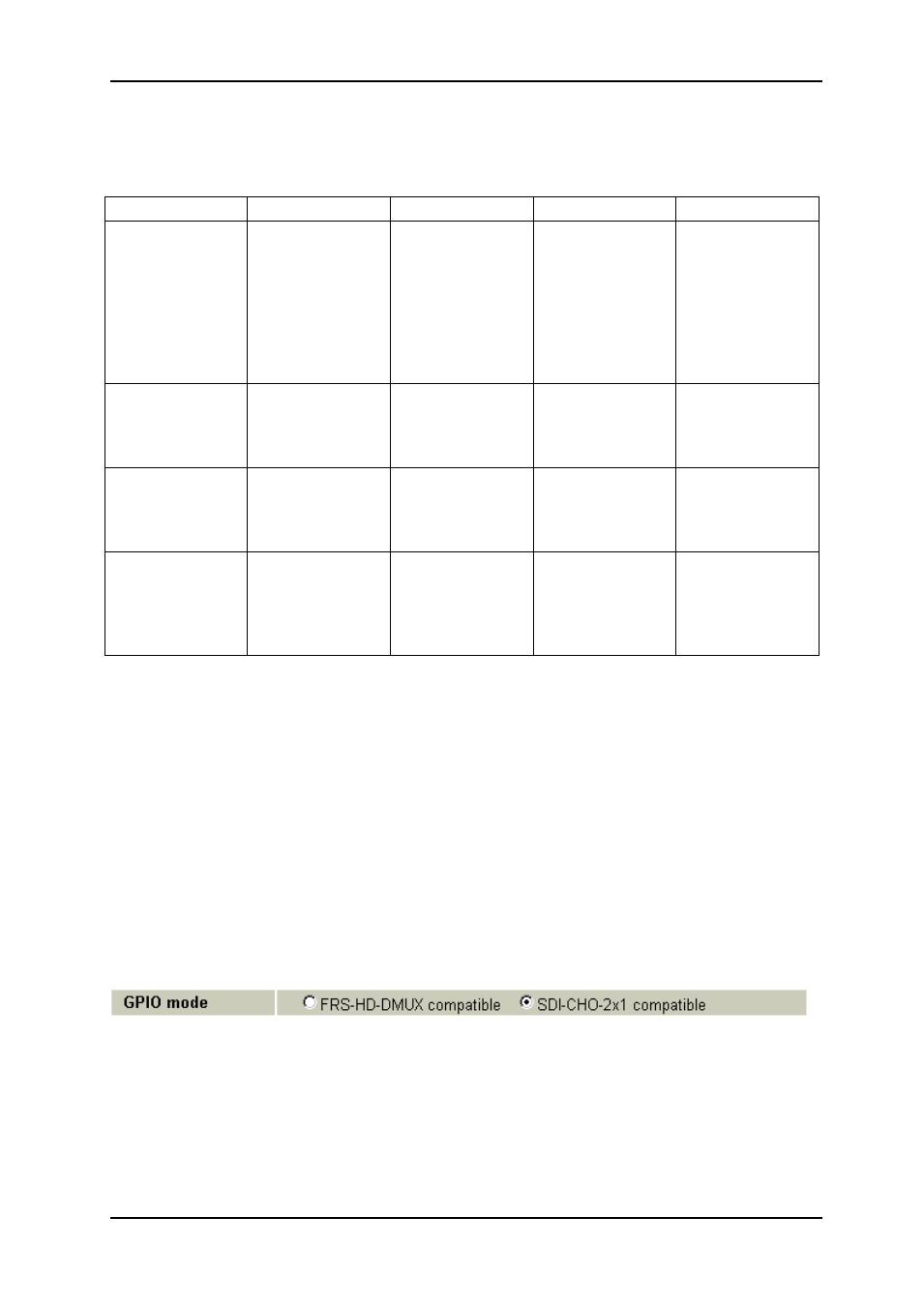
4.2 GPI alarms
The FRS-HD-CHO
can have the GPI outputs to be setup as “change-over style” or “frame
sync style”, either by DIP8 or by Multicon Gyda control. In the graphical user interface of
Multicon Gyda, the selector looks like this:
The
selection “FRS-HD-DMUX compatible” is equal to what the table on the next page refers
to as “frame-synch style”, while “SDI-CHO-2x1 compatible” is equal to the “change-over
style
” of the GPIO lines. As the table on the next page shows, the difference lies in the
behavior of pins 3, 4, and 7.