Oe522-xx round bypass damper assembly, Bypass damper sizing, Bypass damper selection data – Orion System OE742-XX-VAVZ User Manual
Page 17
Form: Orion-OE522-RDBypDmpr-Sub-01F
Page
2 of 2
Bypass Damper Sizing
Because the zones in an Orion System are
controlled using variable air volume, it is
unlikely that all zones will be at design load
at the same time. This zoning allows for
load diversity to be taken into account when
sizing the central HVAC unit. This typically
will provide better comfort with a smaller
HVAC unit than with the use of a constant
volume system. Use a load program to
determine the individual zone loads.
Because of zone diversity the HVAC unit
should be sized for the correct
instantaneous peak load, not the sum of the
peak loads as would be the case when
sizing a normal constant volume unit
system. The Bypass Damper should be
sized to provide for the maximum amount
of air to be bypassed in the system. This is
typically 60 to 70% of the HVAC units rated
capacity. These calculations will be used in
selecting the appropriate Bypass Damper
Size(s).
The Orion Systems utilize a typical low
pressure duct design. To reduce noise
problems, duct pressures should not
exceed 1” W.C..
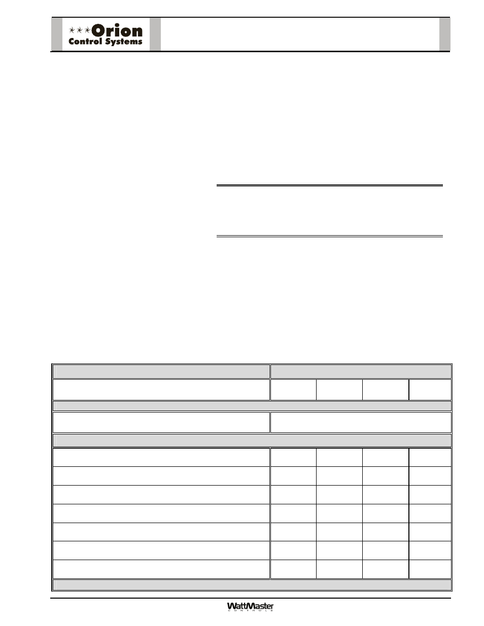
Bypass Damper Selection Data
OE522-XX Round Bypass Damper Assembly
Bypass Air Damper Round Duct Size
(Area Ft
2
)
10”
(0.545)
12”
(0.785)
14”
(1.069)
16”
(1.396)
Velocity Through Bypass Air Damper
FPM
Airflow Through Bypass Air Damper - CFM
(
ΔP
S
inches W.C. w/ Air Damper Full Open)
750
409
(0.01)
589
(< 0.01)
802
(< 0.01)
1047
(< 0.01)
1000
545
(0.01)
785
(< 0.01)
1069
(< 0.01)
1396
(< 0.01)
1250
681
(0.015)
981
(0.015)
1336
(0.015)
1745
(0.015)
1500
818
(0.022)
1178
(0.020)
1604
0.020)
2094
(0.020)
1750
954
(0.034)
1374
(0.030)
1871
(0.030)
2443
(0.025)
2000
1090
(0.040)
1570
(0.040)
2138
(0.040)
2792
(0.030)
2250
1226
(0.07)
1766
(0.05)
2405
(0.05)
3141
(0.04)
WattMaster reserves the right to change specifications without notice
OE522-XX Round Bypass
Damper Assembly
Using the maximum acceptable velocity for a bypass duct
(typically 1750-2250 FPM for minimal noise), find the smallest
damper that will deliver the required CFM as determined by the
load program.
When determining the bypass duct size, be sure to take into
account any transition fittings and their associated pressure
drops. Locate the bypass duct velocity used in the duct design
program in the left hand column of the Bypass Damper Selection
Data table. Move across the table and find the Bypass Damper
size which will provide the acceptable CFM to meet the bypass
airflow requirements.
Note:
Compare the Bypass Air Damper size selected
against the bypass duct size to determine if the next
size up or down will provide acceptable performance
without requiring a transition fitting.
Up to a maximum of two additional Bypass Dampers may be
slaved together with the main Bypass Damper for large bypass
airflow requirements. This design should be reserved only for
situations when it is not practical to use a single large Bypass
Damper. The slaved valves should all be of the same size for
proper control. Divide the total CFM by two or three depending on
how many bypass and slave dampers you will be using and size
accordingly.