Orion-oe519-rectdmpr-sub-01b, Oe519 - rectangular damper, Description – Orion System OE742-XX-VAVZ User Manual
Page 24: Mounting, Damper sizing
Form: ORION-OE519-RectDmpr-Sub-01B.doc
Page
1 of 2
Description
The OE519 Rectangular Damper is used
in applications where rectangular duct is
specified or required because of space
limitations or job requirements. The Rec-
tangular Damper utilizes opposed blades
of airfoil design for improved air flow con-
trol. The Rectangular Damper frame is
made of .080 thick extruded aluminum.
The blades are also made of extruded
aluminum. Blade pins are 7/16” hexagon
shaped aluminum fixed to a Celcon inner
bearing rotating within a polycarbonate
outer bearing inserted in the damper
frame. The Damper linkage is mechani-
cally assembled and located in the
damper frame. The linkage components
are constructed of aluminum, zinc and
nickel plated steel. Blade gaskets are
made of extruded EPDM material and are
secured within an integral slot on the
blade. Jamb seals are of extruded TPE
material for low leakage through the
damper when closed. The control shaft is
1/2” diameter hexagon shaped rod and
can be extended 9” past the damper
frame for connection to the damper ac-
tuator. The damper shaft is shipped re-
tracted into the frame area and must be
adjusted to the required length in the field.
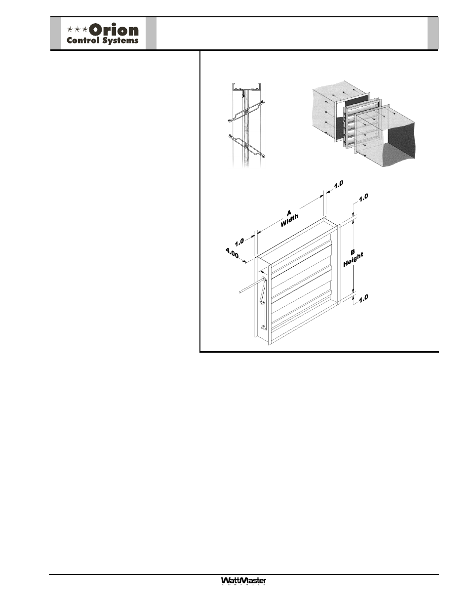
Mounting
The Rectangular Damper should be
mounted in the ductwork according to standard duct installation practices. The rectangular damper should be se-
lected for the nominal inside duct size. All Rectangular Dampers are supplied with 1” flanges all around damper
frame, making the overall damper width and height 2” larger than the nominal inside duct size thus providing for
external flange mounting to ductwork. The damper shaft is shipped retracted into the damper frame. Loosen the
two nuts on the U-bolt that secures the damper shaft to the damper blade and adjust to length. It is recommended
that the shaft length be adjusted so approximately 4” of shaft extends beyond the inside of the damper frame.
Retighten the two nuts on the U-bolt that secures the damper shaft to the blade. After installation of the Rectan-
gular Damper to the ductwork, it is recommended that insulation be applied around any non-insulated surface on
the ductwork where the Rectangular Damper was installed.
Damper Sizing
Use a load program to determine the peak load for each zone. These calculations will be used in selecting the
appropriate Rectangular Damper sizes. The Orion Systems utilize a typical low pressure duct design. To reduce
noise problems, duct pressures should not exceed 1” W.C.
Primary trunk ducts used with Orion systems should not be “undersized”. This is especially true of “pressure de-
pendent” systems. With pressure independent systems this is not as critical. With larger trunk ducts, it is easier to
assure relatively constant pressure to each Rectangular Damper. Runs should be as short as possible, and the
trunk duct system kept as symmetrical as possible to facilitate system balancing. Wherever possible, run the trunk
ducts above corridors and locate the Rectangular Dampers above corridors to reduce the noise in the space and
facilitate service of the valves. Trunk ducts should be sized for no more than 0.1” W.C. drop per 100 ft. of duct,
and a maximum duct velocity of 2000 FPM.
Dimensional Data
Opposed Blade Profile
Flanged to Duct
Installation
OE519 - Rectangular Damper